You can use the Holder Drawing tab to create a custom Tool Holder from a curve or solid.
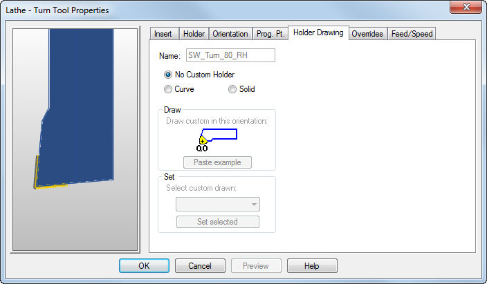
Click the tool preview image to pan and zoom it. The orientation of the preview is determined by the settings on the Options > View > Machine page. Right-click the image to access a context menu.
Name — Specifies the name of the current tool.
No Custom Holder — A default rectangular holder is used based on the Holder dimensions.
Curve — You can select a curve to define the shape of the Holder. This enables you to specify the exact shape of your Tool Holder, so you can check for Holder collisions during simulations.
Paste example — Creates a curve in the shape of the current Holder in the graphics window, which you can use as a guide to create a new curve.
Select a curve from the Select custom drawn list, then click Set selected to save it. The curve is saved in the tooling database independently from the part file. Any subsequent use of this tool in any part file uses the custom holder.
Solid — You can select a solid to define the shape of the Tool Holder. This is the most accurate way to represent the tool holder.
After you have imported and positioned the solid so that the point zero is in the correct place, select Solid, then select it from the Select custom drawn list, then click Set selected to save it. The solid is saved in the tooling database independently from the part file. Any subsequent use of this tool in any part file uses the custom holder.