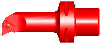
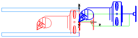
Here is an example of a FeatureCAM turning tool holder:

To use a solid model to accurately define the shape of the tool holder:
- Import the solid model file of the tool holder:
- Select File > Import from the menu to display the Import dialog.
- Select the solid model in the Import dialog, then click Open.
- Click Cancel to close the Import Results dialog.
In this example, a *.x_t solid model of the tool holder is used:
- Optionally rename the solid in the
Part View panel:
- Right-click the solid in the Part View panel and select Rename to display the Rename Object dialog.
- Enter a New Name, then click OK.
- Find the zero point (mounting point) of the solid model holder:
- Select the two faces that point towards the zero point, for example:
- Click Home tab > Display panel > Hide > Hide Unselected. Only the selected surfaces are displayed in the graphics window:

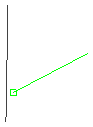
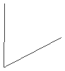
- Click Construct tab > Geometry panel > Line > 2 Points and create a line along the mounting edge of each face, for example:

- Click Home tab > Select & Edit panel > Select > Single or Box Select and select the two faces in the graphics window.
- Right-click on the selection and select Hide Selected from the context menu.
- Click Construct tab > Geometry panel > Edit > Trim/Extend and use the
Trim/Extend tool to extend the lines until they intersect:
- Click Construct tab > Geometry panel > Edit > Clip and use the
Clip tool to clip the ends of the lines beyond the intersection:
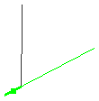
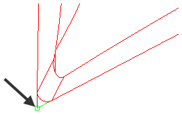
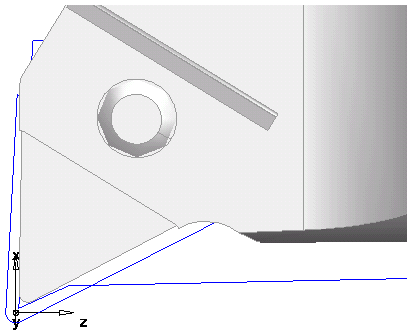
The intersection is the zero point which you can use to position the holder:
- Select the two faces that point towards the zero point, for example:
- Create a reference point to move the holder to:
- On the
Holder Drawing tab of the
Tool Properties dialog, select
Curve, then click
Paste example.
A curve is created in the graphics window.
- Click Home tab > Display panel > Show > Show All Solids.
- Click View tab > Appearance panel > Shade > Unshade All.
An outline of the solid is displayed in the graphics window:
- Select the solid holder in the Part View panel.
- Select Home tab > Select & Edit panel > Transform to display the Transform dialog.
- In the
Transform dialog, select
Translate and
Move, then in the
Distance from 2 points area, click
From
Pick Location
 and select the zero point you sketched earlier in the graphics window:
- Click
To
Pick Location
and select the zero point of the pasted holder curve in the graphics window:
- Click
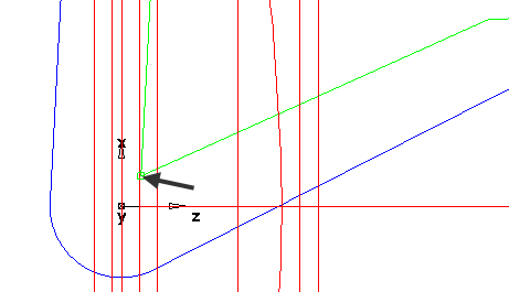
Preview to display a preview of the solid holder's new location of the in the graphics window. The preview is shown in blue:
- Click OK to accept the new location and close the Transform dialog.
- On the
Holder Drawing tab of the
Tool Properties dialog, select
Curve, then click
Paste example.
- Use the Transform tool to move the zero point of the solid holder
 to the zero point of the pasted holder curve
 :
:
- Select the solid holder in the Part View panel.
- Click Home tab > Select & Edit panel > Transform to display the Transform dialog.
- In the
Transform dialog, select
Translate and
Move, then in the
Distance from 2 points area, click
From
Pick Location
and select the zero point you sketched earlier in the graphics window:
- Click
To
Pick Location
and select the zero point of the pasted holder curve in the graphics window:
- Click
Preview to display a preview of the solid holder's new location of the in the graphics window. The preview is shown in blue:
- Click OK to accept the new location and close the Transform dialog.
- Click Home panel > Display tab > Shade Surfaces.
- Select the holder curve you pasted earlier and press the Delete key to delete it.
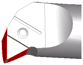
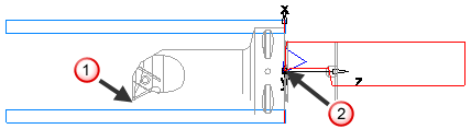
- If you look at the solid holder from the front, there is a recess where the insert sits:
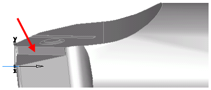
- You must take this recess into account to achieve accurate simulation. To do this:
- Using the
Linear Distance tool, create a measurement of the depth of the recess:
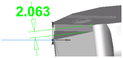
In this example, it is approximately 2mm.
- Select the solid holder in the Part View panel.
- Click Home tab > Select & Edit panel > Transform to display the Transform dialog.
- In the XYZ Distance section, enter 0 for X, -2 for Y, and 0 for Z to move the holder down by 2mm in the Y direction.
- Click
OK.
The solid holder is now in the correct position.
- Click OK to continue.
- Using the
Linear Distance tool, create a measurement of the depth of the recess:
- Set the solid as the holder for the tool:
- On the Holder Drawing tab of the Tool Properties dialog, select Solid, then select the solid from the Select custom drawn list.
- Click Set Selected. The solid holder is displayed in the preview window on the tab and you can see the insert position relative to the holder.
- Click OK to accept the solid holder. The preview on the Tools tab is updated.
- Click OK to continue.
- Hide the imported solid and show the part solid.
- Run a 3D simulation. The solid model that you imported is now used as the tool holder and the simulation is more accurate: