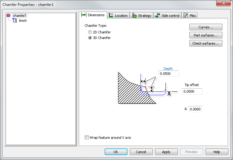
You can use the Dimensions tab of the Chamfer Properties dialog to change the dimensions of a chamfer feature.

Use a 3D chamfer feature to create chamfers from curves that are not in the XY plane, or from non-planar curves.
Enter the Depth of the 3D chamfer, which is a horizontal and vertical (negative) tool offset from the contact point on the input curve (the default is 0.020" or 0.5 mm).
Optionally enter a Tip offset, which is an additional negative vertical tool offset. The default is 0.0.
The Part surfaces and Check surfaces buttons work in the same way as for a 3D surface milling feature, but they are optional for 3D chamfers.
Part surfaces
Use this dialog to pick surfaces you want to gouge-check in your 3D part feature.
- Select the surface(s) in the list or click the Pick surface button and select a surface with the mouse. To pick additional surfaces, click the Pick surface button again before selecting each additional surface.
- Click OK to return to the Feature Properties dialog.
- Click OK and Apply to apply your surface selection to the feature and return to the Feature Properties dialog.
Check surfaces
Check surfaces are surfaces that denote areas that are not milled away. Use this dialog to select surfaces you want to use to limit machining in a 3D feature.
- Select the surface(s) in the list box or click Pick and select a surface with the mouse. To pick additional surfaces, click Pick again before selecting each additional surface.
- Click OK to return to the Feature Properties dialog.
- Click OK and Apply to apply your surface selection to the feature and return to the Feature Properties dialog.
If you select any Part surfaces, they are allowed to be cut to the depth of the chamfer (in other words, the allowance is equal to -Depth).
If you select any Check surfaces, there is a Check allowance attribute on the Milling tab (the default is 0).