Slope boundary — This is the angle that divides the horizontal and vertical regions. Portions of the surfaces with slopes less than this angle are machined with the parallel toolpaths, and the steeper slopes are machined by the Z level.
Slope overlap — This indicates how much the two regions overlap, in degrees. An overlap of 0 means that the two regions are distinct. A value of 10 means that the two passes overlap by 10 degrees.
Horizontal
Select a Spiral or Parallel toolpath for the shallow regions of the feature.
If you are using a Spiral toolpath for the shallow regions, the shape of those regions is automatically calculated based on the Slope boundary and Slope overlap attributes.
Continuous spiral — Enable this option to stop the tool lifting from the surface when machining.
Enable Continuous spiral to have a toolpath that stays in constant contact with a surface, reducing the chance of leaving any dwell or witness marks on the surface caused by regular retract and approaches to the surface.
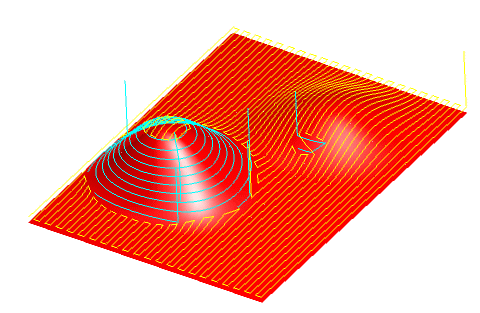
The standard Z level finishing toolpaths creates paths with a constant Z height as shown below. The tool either retracts or feeds along the surface between Z levels.

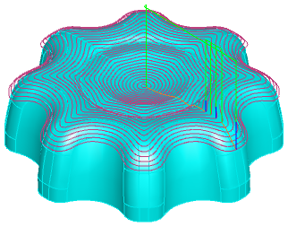
With Continuous spiral enabled, the toolpaths change into a continuous spiral. The toolpaths no longer have a constant Z height.
In to out — The default spiral motion starts at the edge of the feature and moves inwards. Enable this option to start the spiral at the center of the feature and move outwards.
Smoothing — This removes all sharp changes in direction. It works in a similar way to the Toolpath corner % raceline smoothing attribute, but smooths all toolpaths, not just corners.
This example shows a 3D spiral finish without smoothing:
And with smoothing:
If you select to use a
Parallel toolpath, the pass is parallel to the X axis unless you enter a
Parallel angle. Set the
Parallel angle to
90 to be parallel to the Y axis.
Vertical
These attributes control the steeper regions of the feature.
Bottom up — Enable this option cut the Surface feature from the bottom upwards. Disable it to cut top downwards.
Holder collision clipping — Clips the toolpath where the holder or shank collides with a part surface, check surface, or unmachined stock. When selected, the Holder clearance and Shank clearance attributes are displayed on the Milling tab for the operation.
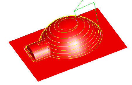
Spiral example
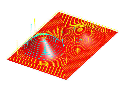
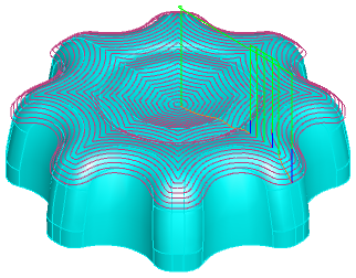
Parallel example