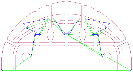
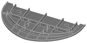
This example aerospace part has several open and closed areas:
This centerline simulation of a Z-level finish toolpath shows the locations of the default start points:

To move the default start points, first create curves that intersect the toolpath where you want the new start points to be.
In the example, the curves are shown in red:
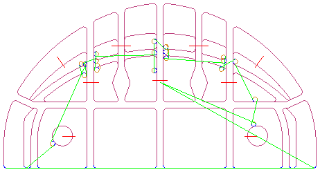
You must use a single curve per toolpath. You can use the Join constructor to create one curve from multiple curves.
Select the curves and click the
Add
 button to add the curves to the list in the
Join Curves dialog.
button to add the curves to the list in the
Join Curves dialog.
Select the Show Preview option to preview the joined curves, for example:
If the curves are not listed in the correct order, select the curve you want to move in the list and use the
Move item up
 and
Move item down
and
Move item down
 buttons.
You can also reverse a curve's direction using the
Reverse selected curve
 button.
Enter a Curve name for the joined curve.
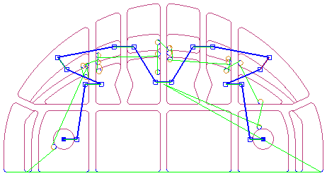
On the Milling tab for the finishing strategy, select the Start point(s) attribute, enter the name of the curve you created and click the Set button to save it.
Another centerline simulation shows that the start points have moved to the intersections of the joined curve with the toolpath, and the toolpath is more symmetrical: