You can use the Plunge tab of the Milling Feature Properties dialog to edit the plunge settings for a Milling feature.
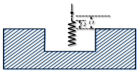
Plunge clearance — Enter the distance above the operation at which the tool feeds.
This is marked as L1 in the diagram.
For deep hole drilling, the drill retracts to this distance between pecks. For milling features, the default is to use the same value for roughing and finishing. As a result, the tool feeds from the top of a feature to the floor before cutting. To make the tool feed down into the feature, set the Plunge clearance for an operation to a negative value, but ensure the value is above the floor of the feature.
To rapid to depth, you can use a negative Plunge clearance, or select Relative plunge.
Relative plunge — Select this option to measure the Plunge clearance from the bottom of the feature instead of the top. Select Relative plunge and use a Plunge clearance of 0 to rapid to depth.
Plunge feed override — Enter the percentage of the Feed setting to use during a plunge into the material. For example, with a Feed attribute of 2000 MMPM and a Plunge feed override of 50%, the plunge feed rate is 1000 MMPM.
First step — To protect the tool from a hardened surface, enter the percentage by which you want to reduce the calculated Plunge feed override for the initial plunge. For example, with a Feed attribute of 2000 MMPM, a Plunge feed override of 50 %, and a First step of 20%, the feed rate of the first plunge move is 200 MMPM; and the feed rate of subsequent plunges is 1000 MMPM.
Z ramp clearance — Enter the distance above the operation at which ramping starts. Z ramp clearance is bound by Plunge clearance.
This is marked as L2 in the diagram.
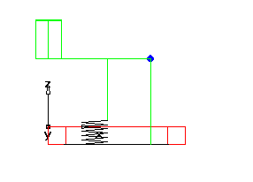
Max. ramp angle — Enter the maximum angle, in degrees, for ramping down to depth. It applies to helical or zigzag ramping. Set this value to 0 to cause a plunge cut.
Max. ramp distance — This applies to linear or helical ramping.
Minimum Ramp — Click this button to display the Minimum Ramp Distances dialog.
Plunge points and Pre-drill points — Specify a point to override the location that the tool plunges or pre-drills into the stock.
This attribute is ignored if there is no plunge move in the operation. For example, if there is no plunge move between a rough and finish operation, the plunge point would be ignored for the finish operation.
A plunge point is ignored if it would result in a gouge to the part, or if the tool would gouge when moving to the starting point of the toolpath. For example if you specify a plunge point that is closer to a wall than the tool radius, the plunge point is ignored.
A warning is displayed in the Operations sheet when FeatureCAM ignores a plunge point.
You can use a curve to specify multiple plunge points.
Start point(s) — Specify a point to override the starting location for a finish operation.
Retract point — This is the point that the tool retracts to after the operation.
Helical ramping — Enable this option to use helical ramping. Disable it to use zigzag ramping.
Helical Options — Click this button to open the Helical Ramp Options dialog.