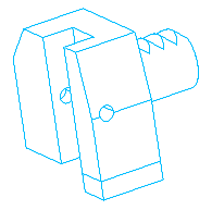
For a turn/mill machine, the holder is held by tool blocks. The tool blocks are most likely supplied by your machine tool vendor. As such, they are stored in the machine design file.
- Each tool block must be represented by a separate solid model.
- Tool blocks should not be associated with the machine through a parent/child relationship.
- The solids must be identified only as a tool block and the appropriate block is displayed along with the selected tools during machine simulation.
- You can model the tool blocks in any location.
There are three basic types of tool block:
- those that hold OD turning tools
-
OD turning (RH)
This tool block holds right-handed turning tools and is mounted on the face of the turret.
-
OD turning (LH)
This tool block holds left-handed turning tools and is mounted on the face of the turret.
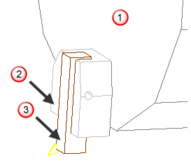
 - Turret
 - Tool block
 - Lathe tool
-
OD turning (RH)
- those that hold X-rotary tools
-
X tool, OD mount
This tool block holds milling tools parallel to the X axis and is mounted on OD of the turret.
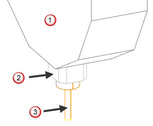 - Turret
- X tool block (OD mount)
- X tool
- Turret
- X tool block (OD mount)
- X tool
-
X tool, face mount
This tool block holds milling tools parallel to the X axis and is mounted on the face of the turret.
 - Turret
- X tool not mounted on OD block
- X tool
- Turret
- X tool not mounted on OD block
- X tool
-
X tool, OD mount
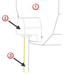
- those that hold ID turning tools (boring bars), drills, and other Z-axis aligned milling tools
-
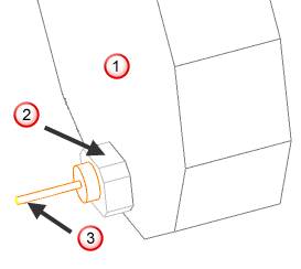
Z tool
This tool block holds boring bars and drills parallel to the Z axis and can be mounted on the OD or the face of the turret.
 - Turret
- ID or Z tool block
- Z tool and holder
- Turret
- ID or Z tool block
- Z tool and holder
-
Z tool
You may want to differentiate between an OD turning tool block for left-handed tool versus a right-handed tool. If you use any left-handed turning tools, add a left-handed tool block.
There is another option for X-rotary and Z-axis tools: you can mount them on the OD of the turret or on the face of the turret. If, when adding a tool location on the turret, you specified the tool position was on the face of the turret, you should use the face-mounted option here in this dialog as well. (The converse is also true, if the OD mounted tool was used as a tool location, specify that the tool block is also OD mounted).
If you cannot mount a tool to the OD of your turret, you do not need to define an OD-mounted tool block. You must, however, have at least one solid tool block defined for every tool type that you intend to simulate. Currently, you cannot use the same solid for different types of tool blocks.
If you do not define an OD-turning tool block, FeatureCAM attempts to use an OD mounted X-tool block for any OD turning tools. In this manner, you can generally define a machine with only two tool blocks, one for OD turning and X-tools, and another for ID boring bars and other Z-tools.
You need only define tool blocks for the main turret. Tool blocks with appropriate transformations are used for the sub-turret automatically.