Note: Ensure
Enable Turn/Mill UI is selected in the
Machine Design Settings dialog to access the lathe design options.
Use the Tool Block dialog to specify solids as tool blocks, specify their positions relative to the tool post, and specify the locations of the tools in the tool blocks.
There are different types of tool blocks.
To display the Tool Block dialog, select Machine Design > Tools panel > Tool Block for Tool Post.
To create a tool block:
- Under This solid is a tool block for tool posts, select a solid to use as the tool block. You can use a block solid positioned out in space, or in place such that it plugs into tool slot #1.
- Under
This UCS will match up with the tool location on the tool post, select a UCS to mate with the tool mounting location on the tool post (shown in the image below).
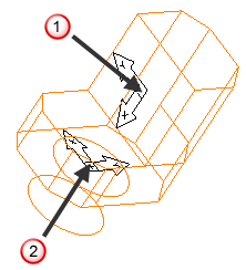
 Tool location
 Mounting location to tool post
If the tool block solid is already in place, you can use the same UCS as the tool location slot #1 on the turret.
- Select which tool posts the tool block can address.
- Select which tool locations on the tool post the tool block can attach to.
- If the tool block can rotate, specify an Additional C Offset to align the rotation angles, for example, use this to change a Z tool into a Y tool. This is added to the other offsets when the tool block is moved.
- Select the Tool Locations tab.
- Click Add to add a new tool location. The Tool Information dialog is displayed.
- Select a UCS to define the tool location on the tool block, or click New UCS Wizard and create one.
- Under Modeled to cut which spindle, select which of the spindles the tool addresses.
- Under
Holds which tool type, select the tool types that can be used at this tool location.
For OD Lathe tools, select the Handedness of the tool.
- Select or deselect Show milling holder and Show turning holder to specify whether to simulate the tool holders in the tool block. You can use this to hide the tool holder when a tool block holds the insert directly.
- Set the
Angular Position of the tool:
- Set Manually — Select this option if your compound holder is rotated manually by the machine operator before running the NC program.
- Programmable — Select this option if the angle of your holder is programmed by the NC code.
- Specify where to locate the tool in relation to the tool location. Select
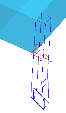
Locates back of tool to specify that the tool location is the location of the back of the tool, or select
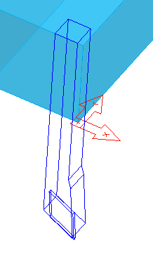
Locates front of tool to specify that the tool location is the location of the tool tip.
Tool location at back of tool holder:
Tool location at tool tip:
- Click OK to add the tool location and close the Tool Information dialog.
- To remove a tool location, select it and click Remove.
- To edit a tool location, select it and click Edit, or double-click it.
- Use the Move Up and Move Down buttons to change the order of the tool locations in the dialog.
- Click OK to close the dialog.