One disadvantage of using Z-level finish is that flat surfaces may fall between the Z-level slices of your operation. The interleave option of Z-level finishing inserts toolpaths in the shallow regions between the slices. This option attempts to finish the entire part with a minimum number of retracts.
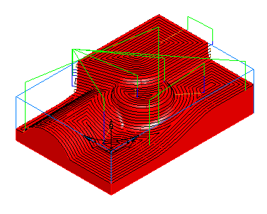
This example shows coarse interleaved toolpaths.
Enable interleaved toolpaths by selecting the Interleave spiral paths option on the Strategy tab.
Interleaved toolpaths are controlled by the Spiral max slope parameter. This parameter controls the slope below which the zigzag toolpaths are inserted. A higher setting of Spiral max slope increases the size of the zigzag or spiral region. In general, this parameter should be set to a value less than 40, because the zigzag toolpaths should be limited to surfaces with slight slopes.
When using the interleaved technique, Z level toolpaths are always calculated using the specified Scallop height, instead of an explicit Z increment. How accurately the toolpaths fit the surfaces is controlled by the Tolerance parameter. To minimize retracts, you may also have to adjust the Stepover rapid distance.
There are four different styles of toolpaths that can be created for the shallow regions.
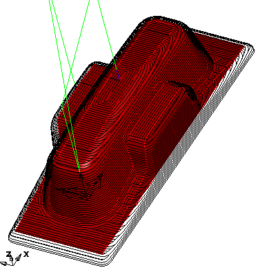
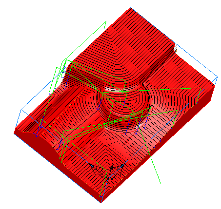
If you select Closed spirals on the Strategy tab, but deselect the Spiral attribute on the Milling tab, offset toolpaths are generated.
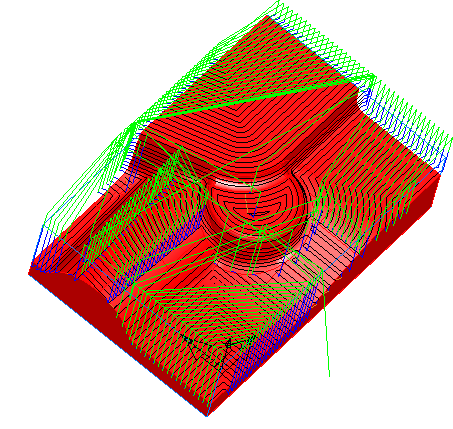
If you select Closed spirals on the Strategy tab and select the Spiral attribute on the Milling tab, continuous spiral toolpaths are generated.
If you deselect Closed spirals on the Strategy tab and select bi-directional in the Cut Direction dialog (accessed by clicking the Direction button) on the Milling tab, zigzag toolpaths are created.
If you deselect Closed spirals on the Strategy tab and select Uni-directional in the Cut Direction dialog (accessed by clicking the Direction button) on the Milling tab, you can create toolpaths that cut in a single direction.
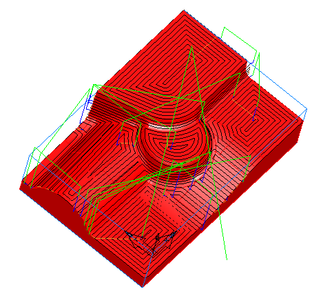
Remove shallow slices — In addition to the style of cut on the shallow regions, you can also change the toolpaths with the Remove shallow slices option. This example shows Z finish toolpaths with Remove shallow slices selected.
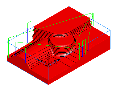
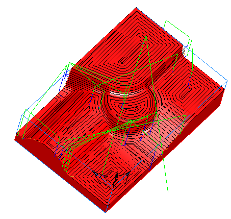
Without Remove shallow slices selected, toolpaths are inserted between each slice. This results in the shallow regions being relatively flat.
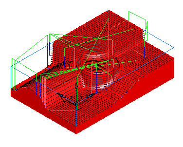
With Remove shallow slices selected, the slices in the flatter regions are removed. This results in the removal of some possibly unnecessary slices, but shallow regions tend to be larger and the shallow toolpaths tend to vary more in the Z direction.