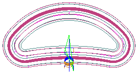
This example uses a 5-axis swarf and two 5-axis trim strategies.
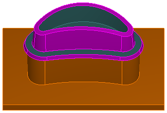
Viewing a centerline simulation from the top, you can see that the default start point for the 5-axis swarf operation is at the lower right of the part.
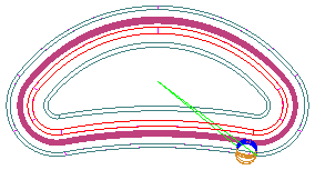
The default start point for the upper trim operation is at the lower left:
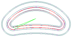
And the default start point for the lower trim operation is at the lower right:
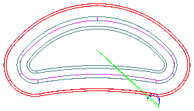
To override the default start points, you must create a curve that intersects the toolpaths at the locations of the new start points. In this example, the curve is shown in blue:
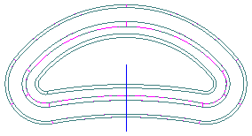
On the Milling tab for each strategy, select the Start point(s) attribute, enter the name of the curve you created and click the Set button to save it.
A centerline simulation of all three operations shows that the start points are now aligned along the curve:
