5-axis position menu — There is often an alternate orientation option for accessing a face. Select from:
- Standard — The default orientation.
- Alternate — The alternative orientation to the default.
- Use Post Preference — Uses the position (Positive or Negative) set in XBUILD in the Five Axis dialog for the Preferred orientation of the primary rotary axis option.
- Use Axis Limits — Allow FeatureCAM to select the orientation that best fits within the axis limits set in the MD file.
Axial offset — This attribute offsets the lowest position of the toolpath along the tool axis. Positive numbers offset the toolpath towards the tool holder, negative numbers away.
Check allowance — Enter the minimum distance that you want to leave around check surface(s). If left blank for a roughing pass, the Finish allowance value is used. If left blank for a finishing pass, the Leave allowance value is used. You can enter a positive or negative value. Set Check surfaces on the Dimensions tab.
Check axial allowance — Enter the amount of axial (Z) material to leave on a check surface. If you enter a value for Check axial allowance, the value for Check allowance is applied to radial (XY) check surfaces only. If you leave Check axial allowance blank, the value for Check allowance is applied to axial and radial check surfaces. You can enter a positive or negative value.
Direction — Click this button to open the Cut Direction dialog.
Holder Collision Clipping — Clips the toolpath where the holder or shank collides with a part surface, check surface or unmachined stock. Select Holder collision clipping on the feature's Strategy tab to enable it. When enabled, these options are displayed:
- Holder clearance — Enter the clearance distance for the tool holder. The toolpath is clipped where the tool holder moves within this distance of a part surface or check surface.
- Shank clearance — Enter the clearance distance for the tool shank. The toolpath is clipped where the shank moves within this distance of a part surface or check surface.
Index X coordinate — Optionally enter the absolute X coordinate to use for the index retract move.
Index Y coordinate — Optionally enter the absolute Y coordinate to use for the index retract move.
Index Z coordinate — Optionally enter the absolute Z coordinate to use for the index retract move.
Orientation angle — Enter the initial C-axis position of the part in the machine at the start of the operation.
Leave allowance — Enter the amount of material to leave after a finish pass. You can enter a positive or negative value. You can enter a negative number, up to minus the tool radius, to allow for shrinkage or spark gaps, and the part is machined into the part surfaces by the negative amount specified. If unset, Leave allowance defaults to 0.
Leave axial allowance — Enter the amount of axial (Z) material to leave on a feature after the Finish pass. If you enter a Leave axial allowance, the Leave allowance is applied to radial (XY) material only. If you do not enter a Leave axial allowance, the value for Leave allowance is applied to axial and radial material. You can enter a positive or negative value.
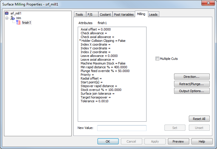
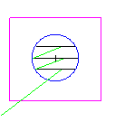
Min. rapid distance % — Enter the minimum distance, as a percentage of the tool diameter, that the tool can use a rapid move for. Moves smaller than this distance use a feed move.
Minimum rapid distance applies to 2.5D milling. Specify the value as a percentage of tool diameter.
This example shows a feature cut with a value of 400%:
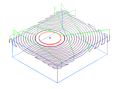
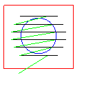
This is the same example with Min rapid distance set to 10% and the tool retracts and rapids between passes.
Multiple Cuts — This enables multiple passes down the tool axis.
New Value — To change the value of an attribute in the list, first select it, then enter the new value. Click the Set button to save the new value.
Output Options — Click this button to open the Output Options dialog.
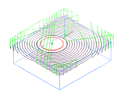
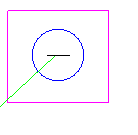
Radial offset — Enter the distance to offset the toolpath in the direction perpendicular to the tool axis. The default is zero.
|
|
|
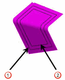
 Trim with no radial offset
 Trim with
5 mm offset
Trim with
5 mm offset
Reset All — Click this button to reset all of the attributes on the tab to their default values.
Retract/Plunge — Click this button to open the Retract and Plunge dialog.
Start point(s) — Override the default start point(s) of a toolpath by entering the name of a curve that, when projected, intersects the toolpath at the point you want. You can use a curve with multiple segments to set multiple start points for a toolpath, and alternating segments are used to set the start points.
Set — You must click the Set button to save a New Value for the selected attribute.
Stepover rapid distance — This is used to determine whether to feed or rapid between toolpaths.
Stock overcut %
Overcut % applies to three types of surface milling features:
- spiral toolpaths designated as a boss on the stock page
- features cut with projection milling technique that do not have an explicit boundary curve
- some Z level rough passes.
In the boss case this attribute applies only to how the toolpaths behave around the stock boundary.
For other 3D surface milling features, use the cut allowance feature described on the Stock tab. The Overcut % option applies only if Use stock dimensions is selected on the feature's Stock tab.
Overcut % specifies what percentage of the tool approaches or passes beyond the stock boundary.
It can have a value between -100 and 100 with the following meanings:
0 puts the centerline of the tool on the stock curve.
100 overcuts the region by a tool radius.
-100 stops one tool radius short of the stock curve.
Target horsepower — This is the ideal [horse] power for the specified width/depth of cut and feed rate on the specified stock material type.
Tolerance — This attribute controls how accurately the toolpath follows the surface. If your part appears faceted, set the tolerance to a lower value.
Unset — Click this button to return the value of the selected attribute to its default value.