The Tool Axis Limits dialog controls angular limitations of the machine toolpath which therefore limits the angle at which a tool can be positioned while cutting a multi-axis toolpath.
Select what happens when the angular limits are met or exceeded:
- Remove toolpaths — This removes the toolpath outside the angular limit.
- Leave tool at Limit — This keeps the tool axis at the machine limit on reaching an angular limit.
Set the Elevation and Azimuth angle:
 This shows the
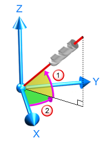
elevation angle, which is the angle from the Tool Axis vector's orthogonal projection onto the XY plane toward the positive Z-axis, to the Tool Axis vector. The elevation angle is between -90 and 90 degrees.
This shows the
elevation angle, which is the angle from the Tool Axis vector's orthogonal projection onto the XY plane toward the positive Z-axis, to the Tool Axis vector. The elevation angle is between -90 and 90 degrees.
 This shows the
azimuth angle, which is the angle from the positive X axis toward the positive Y axis, to the Tool Axis vector's orthogonal projection onto the XY plane. The azimuth angle is between 0 and 360 degrees.
This shows the
azimuth angle, which is the angle from the positive X axis toward the positive Y axis, to the Tool Axis vector's orthogonal projection onto the XY plane. The azimuth angle is between 0 and 360 degrees.
Elevation angle — This defines the angular limits of the machine tool above the azimuth plane; 0 is in the azimuth plane, 90 is along the axis perpendicular to the azimuth plane.
Azimuth Angle — This defines the angular limits of the machine tool in the azimuth plane.
Project to Plane — This is the same as setting the elevation angle to zero. Because the elevation angle is fixed, this usually produces a 4-axis toolpath. If the stock Z axis is not aligned with a rotary axis of the machine tool, a 5-axis toolpath may be produced.
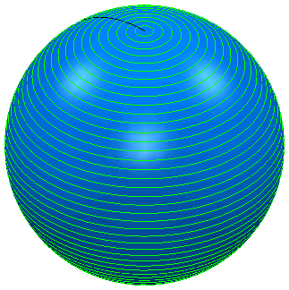
The example below shows you how to transpose the angular limits on the machine tool to the Azimuth and Elevation limits. These examples all use a sphere with an Isoline or Flowline Projection toolpath. If no tool axis limits are imposed, you will see the following toolpath: