Tessellation is the process of tiling the curves' shapes with polygons. Flame offers different tessellation methods for use with 3D Text and 3D Shape nodes:
- Tessellation Type box
- Select the tessellation type you want to apply to the geometry. More settings appear if you select Delaunay or Medial Axis. Medial Axis is not available when using the 3D Shape node.
-
Standard (GLU) is the fastest tessellation option, although it is also the least efficient.
-
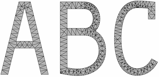
Delaunay generates a mesh composed entirely of triangular polygons. This method gives consistent and predictable results, and in particular, it will not give different results if the tessellated objects are rotated.
-
Medial Axis creates concentric contour lines along the medial axes (averages between the input boundary curves), morphing from one boundary shape to the next.
The Wireframe box is also provided in the Tessellation menu. It is the same setting as in the Geometry tab, but repeated here for ease-of-use.
-
Each method has its own set of options, described in the sections that follow.
Standard (GLU)
The Standard (GLU) tessellation method is the legacy tessellation option; while being very light in its processing requirements, it is also the least efficient and precise. And compared to Delaunay and Medial Axis tessellation methods, it has no options to fine-tune the resulting tessellation.
Delaunay
The Delaunay tessellation method (or more precisely, constrained Delaunay tessellation) generates a mesh composed entirely of triangular polygons. This method gives consistent and predictable results, and in particular, it does not give different results if the curves are rotated.

With this method, there are several options for fine-tuning the tessellation further.
- Min Angle field
- Displays the smallest value of angle that the polygons can have. If a triangle contains an angle that is smaller than this value, it gets replaced by better-shaped ones. Eliminating small-angled triangles gives a more uniform shading and is more suited for deformations.
Min Angle = 20
- Max Area field
- Displays the largest value of area that the polygons can have. If a triangle is larger than this value, it gets replaced by smaller ones. This allows the polygon mesh to be deformed more smoothly.

Max Area = 5
- Max Vertices field
- Displays the total number of new vertices that can be added by the Minimum Angle and Maximum Area options. 0 by default.
Use this option as a precaution against accidentally setting the other options to values that would create huge amounts of geometry with long processing times.
It is not recommended that you rely on this option to control the final number of vertices because it can force the tessellation to stop before the process is completed, thereby giving an unpredictable combination of polygon shapes and sizes.
- Boundary Split box
- Select an option to control tessellation along boundaries.
Select: To: Free Allow the boundary edges along the outer contour and inner holes to be split further during tessellation. This is particularly useful for text and other shapes that may contain straight edges that need to be deformed smoothly.
None (Contour Only) Allow boundary edges along inner holes to be split, but not boundary edges along the outer contour. Note that this may affect the uniformity of the mesh if you enabled Min Angle or Max Area.
None (Contour and Holes) Prevent any boundary to be split. Note that this may affect the uniformity of the mesh if you enabled Min Angle or Max Area.
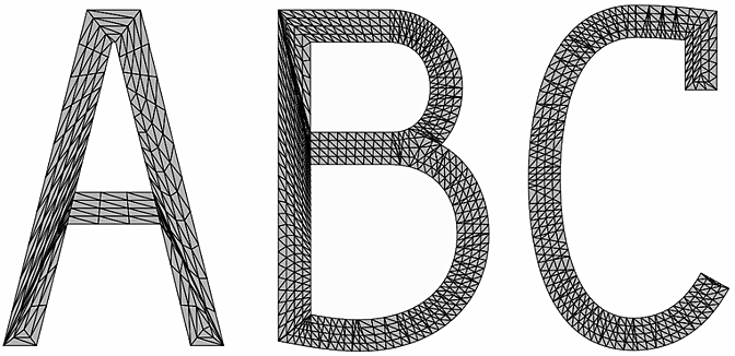
Medial Axis
The Medial Axis tessellation method creates concentric contour lines along the medial axes (averages between the input boundary curves), morphing from one boundary shape to the next. This method creates mainly quads with some triangles, so it is well-suited for subdivision surfaces.

With this method, there are several options for fine-tuning the tessellation further.
- Loops field
- Displays the number of loops used in the tessellation, modified by the Adaptive toggle.
Loops = 2
- Adaptive button
- Enable to set the Loops field as the average number of medial axes drawn and to keep the distance between them fairly constant. Disable to set the Loops field as the exact number of medial axes drawn per boundary (rounded to the nearest integer).
- Backtrack Length field
- Displays the tessellation value at the extremities. Editable.
Set to: To have: 0 The medial axis intersects boundaries at each point of concavity, which can often create many small triangles especially in sharp extremities. Positive value The medial axis does not extend completely to the boundary and the remaining area is tessellated with a fan shape. Negative value Sharper embossing effects
- Split Edges to Enhance button
- Enable to add vertices to allow the contour lines to follow the medial axes more accurately. Turn this option off if there are no holes in the geometry; otherwise, there may be shading artifacts along internal curves.
- Edge Tessellation box
- Select an option to control the shape of the polygons.
Select: To: None Have long edges that are not split. This results in fewer polygons and lighter geometry, but the resulting long, thin polygons may not deform well. Equal on Both Sides Have a tessellation made of squarer polygons that deform better, at the cost of a heavier tessellation.