Motion constraints specify the intended motion between assembly components. Because they operate only on open degrees of freedom, they do not conflict with positional constraints, resize adaptive parts, or move grounded components.
Motion constraints are shown in the browser. When clicked or the cursor hovers over the browser entry, constrained components are highlighted in the graphics window.
The Drive Constraint command is not available for motion constraints. However, parts constrained by motion constraints can be indirectly driven according to the specified direction and ratio.
- Access
- Ribbon:
Assemble tab
 Relationships panel
Constrain
Relationships panel
Constrain
 , and then click the Motion tab.
Type and Solutions
Specifies the constraint type and illustrates the solution that shows the intended motion between selected components. May be applied between linear, planar, cylindrical, and conical elements.
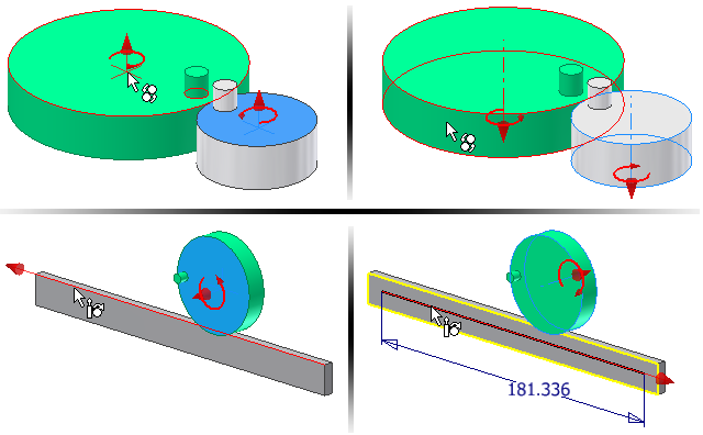
- Rotation constraint

- Specifies that the first selected part rotates in relation to another part using a specified ratio. Typically used for bearings, gears and pulleys.
- Rotation-Translation constraint

- Specifies that the first selected part rotates in relation to translation of another part using a specified distance. Typically used to show planar motion, such as a rack and pinion.
Selection
Selects geometry on two components to constrain together.
- First Selection

- Selects the first component. Select a planar face to specify the ratio or distance. Select a cylindrical face to calculate the ratio or distance. The selection is previewed in red in the graphics screen. To end the first selection, click Second Selection.
- Second Selection

- Selects the second component. Select a cylindrical face on a rotational component or a linear edge on a translational component to calculate the ratio or distance. The selection is previewed in green in the graphics screen. To select different geometry on the first component, click First Selection and reselect.
- Pick Part First

- Limits the selectable geometry to a single component. Use when components are close to or partially obscure one another. Clear the check box to restore selection mode.
Ratio or Distance
Specifies the movement of the first selected component relative to the second selected component.
- Ratio
- For Rotation constraints, the ratio specifies how much the second selection rotates when the first selection rotates. For example, a value of 4.0 (4:1) rotates the second selection four units for every unit the first selection rotates. A value of 0.25 (1:4) rotates the second selection one unit for every four units the first selection rotates. The default value is 1.0 (1:1). If two cylindrical surfaces are selected, A default ratio computes and displays that is relative to the radii of the two selections.
- Distance
- For Rotation-Translation constraints, the distance specifies how much the second selection moves relative to one rotation of the first selection. For example, a value of 4.0 mm moves the second selection 4.0 mm for every complete rotation of the first selection. If the first selection is a cylindrical surface, a default distance computes and displays that is the circumference of the first selection.
Note: Although The ratio and distance parameters are used to specify the amount of movement for the second selection with respect to the first selection. However, the constraint is bidirectional. If the second selection is moved, the first selection moves by an inverse amount of either the ratio or distance, as appropriate to the constraint type.
More

- Name
- Sets the constraint name. Creates a unique name for the constraint in the browser. You can enter a name or leave blank and a default name is automatically created.