The sketch geometry for a lofted flange can represent the inside or outside face of the sheet metal material, or it can represent the material midplane.
Usually, a closed profile defines both ends of a transitional shape. These designs are used for duct work, ventilation exhaust hoods, and any number of container shapes.
You can flatten lofted flange features created with closed profile sketches at either end by adding a Rip feature.
You can output lofted flange features to either a smooth, die-formed model, or to a model you can produce using straight bends with Press Brake.
Lofted flange examples
The following illustrations show various input and output options for Lofted Flange features. The closer image shows the Lofted Flange perpendicular to sketch planes.
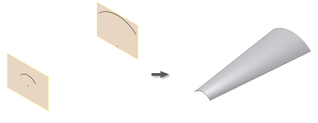
Similar Open Profiles - Die Formed Output
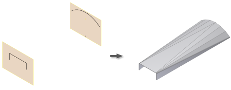
Dissimilar Open Profiles - Press Brake Output
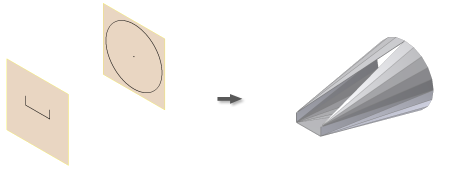
Closed to Open Profiles - Press Brake Output
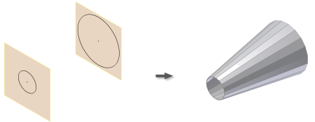
Circular Closed Profiles - Press Brake Output
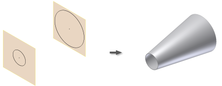
Circular Closed Profiles - Die Formed Output

Circular to Sharp-corner Rectangle Closed Profiles - Press Brake Output

Polygon to Sharp-corner Rectangle Closed Profiles - Die Formed Output

Radius-corner to Sharp-corner Rectangle Closed Profiles - Press Brake Output

Non-Parallel Circular Closed Profiles - Die Formed Output