You can create a lofted flange for die formed or press-brake output, and edit the bend and bend zone.
Create Lofted Flange for Die Formed or Press Brake Output
For die formed output, create a smooth, die formed transitional shape from two sketch profiles.
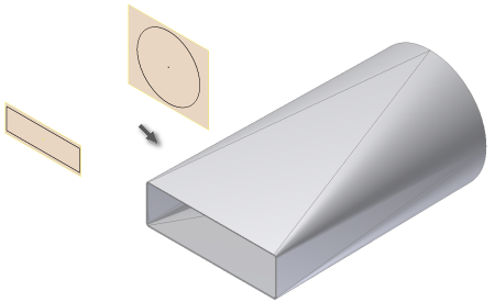
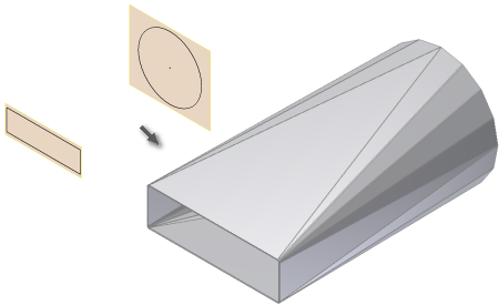
For press brake output, create a transitional shape from a flat face and a cylindrical bend face using two sketch profiles and appropriate options.
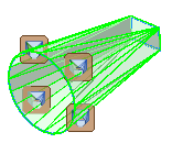
If Enable/Disable feature preview is selected, the Lofted Flange result previews.
After you create a Lofted Flange feature using either Die Form or Press Brake, you cannot edit the output option of the feature. You can delete the feature without deleting the profile sketches, and recreate using the alternate output type.
- On the ribbon, click
Sheet Metal tab
 Create panel
Lofted Flange
Create panel
Lofted Flange
 .
.
- Click Profile 1
 and then click the visible sketch geometry that defines the first profile of your Lofted Flange.
- Click Profile 2
 and then click the visible sketch geometry that defines the second profile of your Lofted Flange.
- If there are two or more solid bodies in the part file, click the Solids selector to choose the participating solid body.
- (Optional) If a body exists, click New Solid to create a new body.
- (Optional) Do one of the following:
- Select the Follow Defaults checkbox to link the material thickness and rules to the Default setting.
- Clear the Follow Defaults checkbox and click the drop-list to specify a unique material thickness and rules from the predefined list.
- Do one of the following in the Lofted Flange dialog box Shape tab:
- To create a lofted flange for die formed output, click Die Form
 .
.
- To create a lofted flange for press brake output, click Press Brake
 .
.
(Optional) Select Converge to specify that bends of the flattened faceted sections converge near a point.
- To create a lofted flange for die formed output, click Die Form
- (Optional) For press brake output, select an alternative Facet Control and enter a corresponding control value.
- A Chord Tolerance. Determines the maximum distance from the arc segment to the face segment chord.
- B Facet Angle. Determines the maximum angle to the chord segment at the facet face vertex.
- C Facet Distance. Determines the maximum width of the facet face (length of the chord) when subdividing the arc profile.
- (Optional) Specify a Bend Radius value and Unfold Rule that differs from the active Sheet Metal Rule.
Edit Bend and Bend Zone in Lofted Flange Feature
You can change the facet control type and parameter for a bend zone within a Lofted Flange feature.
You can also change the bend radius and unfold rule for individual bends within a selected bend zone of a lofted flange.
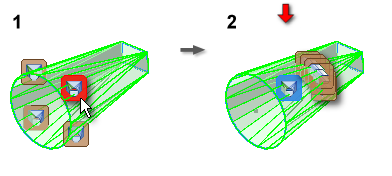
- Right-click the bend child-feature of a lofted flange, and click Edit Bends.
- (Optional) To edit a bend, click the Bend Edit glyph, and then specify a different value for Bend Radius or Unfold Rule.
- (Optional) To edit a bend zone, click the Bend Zone Edit glyph in the bend zone you want to edit, select the checkbox on the Bend Zone Edit dialog box. Then select an alternative facet control option and enter a new value to specify absolute number of facets.