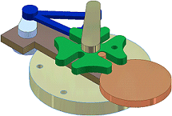
Learn how to get help with kinematic investigation

- You can drive relationships through a range of steps or distance to conduct motion studies for fully and partially constrained systems.
- You can use the Contact Solver on an isolated set of components to detect contact between components. You move the components or drive relationships to simulate a mechanical motion.
- You can turn on Collision Detection when driving relationships. If a collision occurs, the motion stops. Using the values at the collision point, you can reposition components as needed.
How do relationships affect motion analysis?
Many mechanisms do not have permanent relationships between two parts that move in unison, such as boxes on a conveyor belt. One part moves and comes into contact with another and the second part, which has open degrees of freedom, moves in response.
In an assembly, you can drag components into position and, when you press ALT, automatically constrain the components in the inferred positions. By strategically omitting constraints that would not be present in the real mechanism, you allow components to move in intended motions.
Use the contact solver or collision detection, usually in combination with driving constraints. You can determine whether the components are positioned correctly to complete the intended motion.
What does the contact solver do?
The contact solver isolates selected components in a contact set so you can determine whether the components behave in a mechanical motion as expected. You designate components to include in the contact set, and then move the components or drive relationships to simulate the action.
Some examples include:
- Simulating the flow of a product through a stamping machine. You can validate that the loading mechanism pushes the holding jig to the correct location and pushes the old jig out of position.
- Simulating transmission synchronizers, which depend on calibration teeth to bring a collar shaft up to speed before engaging driving gears.
- Analyzing a cam with inconsistent contact. A machine with a cyclic behavior has a trip sensor to indicate when a process step is complete. Normally, the sensor is in a rest state, with a spring holding it in place. A wheel is located on the end of the sensor arm, to reduce wear when a cam surface comes in contact.
You can turn off visibility or the enabled state to remove a component from analysis for contact, collision, or interference. Right-click the component in the browser or graphics window and clear the check mark from one or both options. Reference components are analyzed regardless of visibility or enabled status.
When can components be added to a contact set?
You can add a component to a contact set at any time, even when the Contact Solver is not active. The component is marked in the browser with a special icon to indicate that it is part of the contact set. When you want to test the contact set components, activate the Contact Solver. On the Tools tab, Analysis panel, click Contact. The default setting becomes active.
Usually, the default setting includes only the members of the Contact Set. To include all components in the analysis, click
Tools tab  Options panel
  Document Settings
  Modeling tab. In the Interactive Contact box, select the All Components setting.
How is a collision reported?
Collision detection is separate from detecting contact between components. You turn collision detection on when you drive constraints.
You can analyze components for collision without adding them to a contact set. If the components are in a contact set, contact can push another component rather than report a collision. An exception is if contact occurs between two parts and one of the parts that must push cannot move (it is grounded, for example). When driving relationships and you select the Collision Detection check box on the Drive dialog box, a message reports the collision. Otherwise, the mechanism stops.