Use welding symbols from the model, or create nonassociative symbols for caterpillars and end fills.
What's New: 2019.2
 |
You can manually add weld annotations to a drawing view even if there are no weldments defined in the model. To change a weld annotation, you select the annotation and change values in the dialog box. |
The annotations (caterpillar, end fill, and welding symbol) are not associated to weldments in the model file and do not update if the model changes.
If welding symbols or end fills were created in the model, you can retrieve them in the drawing view. Welding symbols and end fills update with changes to the model.
Add or edit welding symbols
Use Welding to create a welding symbol with a leader line. The line type, line weight, color, and gap for the symbol are determined by the weld symbol style.
 Get Welding Symbols.
If there are no model welding symbols, you can make a nonassociative welding symbol in the drawing view.
|
|
|
 . Learn more about presets -
To edit a nonassociative welding symbol, right-click a welding symbol, and select Edit Welding Symbol. In the Welding Symbol dialog box, change values as needed, and click OK. Welding symbols retrieved from the model must be edited in the weldment assembly.
Add or edit weld caterpillars
Use Caterpillar to add weld caterpillars to geometry in a drawing view. The caterpillar type, size, angle, and other formatting is determined by the weld bead style.
Get Welding Annotations. If changes are made to the fillet bead in the model, the length of the caterpillar edge updates in the drawing view, but you must manually edit the caterpillar to change the leg length.
If there are no model caterpillars, you can make a nonassociative welding symbol in the drawing view.
|
|
|
Changing the caterpillar side - Once you have placed the arc legs of a caterpillar on the side of an edge, you can change the side on which they are placed. To do this, select the type for both sides in the Type area of the dialog box before you reselect the single side option. Once you have reselected the single side option, the caterpillar follows your cursor from one side to the other side as you move across the edge in the drawing view.
Changing the caterpillar from an entire edge to Start/Stop - Placing a caterpillar requires that you select an edge. If after selecting the edge you decide that the caterpillar should only display along a portion of the edge click Start/Stop on the Style tab of the dialog box and then select the start and stop points along the edge. The points that you select do not have to be geometric points - they can be approximate locations.
To edit, right-click a caterpillar, and select Edit Caterpillar. In the Weld Caterpillars dialog box, enter new values as needed, and click Apply. Click OK to close the dialog box.
Add or edit weld end fills
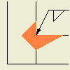
Use End Fill to add 2D end fill annotations to geometry in a drawing view. The size and other formatting is determined by the weld bead style.
Get Welding Annotations. If changes are made to the end fills in the model, end fills in the drawing update. If you customized the leg length of a preset type, you must manually edit the size.
If there are no model caterpillars, you can make a nonassociative welding symbol in the drawing view.
|
|
Custom Shape End Fill - To define a custom end fill, follow steps 1-4 above. Then, define the end fill in the graphics area. When done, click Apply or OK. |
To edit an end fill, select the end fill on the drawing view, right-click and select Edit End Fill. On the End Fill dialog box, change values as needed or select an applicable preset. Click Apply to apply the changes and continue editing. When finished, click OK to close the dialog box.