What's New: 2020
On the ribbon, use
Assemble tab  Relationships panel
Joint
Relationships panel
Joint
 to place a joint between two assembly components.
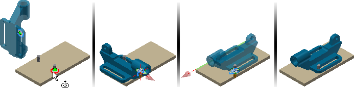
Use Joint to position components and define motion
To begin, place the components in an assembly file.
- Start the Joint command.
The default connection type is Automatic. Automatic determines the joint type based on the following rules:
- Rotational is selected if the two selected origins are circular.
- Cylindrical is selected if the two selected origins are points on a cylinder.
- Ball is selected if the two selected origins are points on a sphere.
- Rigid is selected for all other origin selections.
Note: A Slider connection cannot be specified using a selection rule.
 Select the origin on the moving component.
Tip: Click Ctrl after the necessary component highlights to limit selection to the component.
Select the origin on the moving component.
Tip: Click Ctrl after the necessary component highlights to limit selection to the component.-
The default origin selection is inferred directly from the geometry. For origin that cannot be inferred directly, make a selection from the context menu:
- To create a joint origin between 2 faces, select Between Two Faces, and specify a virtual midpoint between two faces, by selecting two faces and one point.
- To create a joint origin and position it an offset distance from the origin, select Offset Origin. Drag the manipulator arrows or input offset value to change the Origin location. Pick a reference geometry to align the Origin with.
 Select the origin on the stationary component.
- If necessary, change the joint type.
 If necessary, use Flip component to reverse the positive direction.
 If necessary, select Align 1 and pick one of the following to specify the alignment direction:
- A planar face, point, or edge on the moving component.
- A work plane/work axis/work point from the browser or the graphic window(if visible). If Align 1 is point selection(sketch point or work point), Align 2 must also be point selection.
 If necessary, select Align 2 and make a selection on the stationary component to specify the alignment direction.
 To change the alignment direction, select Invert alignment.
- Click Apply or OK to complete the operation.
Use Limits to define range of motion
To define a limit:
- Create or edit a joint.
- Open the dialog box. and click the Limits tab.
Tip: If the dialog box is not available, press the three dots in the min-toolbar to display.
The availability of the Angular or Linear options depends on the joint type. For example, a Rotational joint supports Angular limits, but Linear limits are not available.
Note: Limits are not available for Rigid joints. - Set the necessary Start, Current, and End values.
- Click OK.
A relationship with a defined limit is marked with a +/- symbol in the browser.
Lock or Protect joint
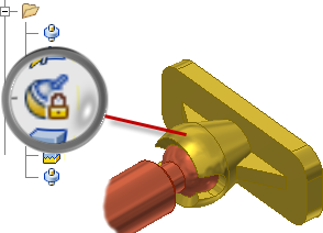
- Lock a relationship to maintain the current position. Lock differs from grounding a component. Grounding eliminates all degrees of freedom, and fixes the component position in space. Lock eliminates all motion, but allows the component to change position when related components move.
- Protect a relationship to warn if added relationships violate the necessary degrees of freedom.
- Locate the relationship in the browser.
- Right-click the relationship, and select Lock or Protect in the context menu.
- To remove the condition, clear the check mark.