Sets the format of dimension styles used in drawings.
The dimension style is a substyle of the standard, but format may be defined regardless of the active standard style. The dimension style references text and leader styles as substyles for formatting.
Access
Ribbon:
Manage tab
 Styles and Standards panel
Styles Editor
Styles and Standards panel
Styles Editor
![]() . In the Style and Standard Editor dialog box, click Dimension in the browser. Click one of the listed styles to view or edit. You can also expand Dimension in the browser, and then click one of the styles.
. In the Style and Standard Editor dialog box, click Dimension in the browser. Click one of the listed styles to view or edit. You can also expand Dimension in the browser, and then click one of the styles.
For the current document, you can click:
- Back to return to the previously edited style. You are prompted to save the previous edits.
- New to create new styles. Select the Add to Standard check box to add to the available styles list in the active standard style.
- Save to save changes to an existing style in the current document.
- Reset to return style values to the saved values.
- Filter to show Local Styles, Styles in the Active Standard, or All Styles in the browser.
- Import to use the Import Style Definition dialog box to import a style exported from another document.
On the Manage tab, Styles and Standards panel, you can also use these commands:
- Click Update to refresh the style list in the browser pane to include new or changed styles in the library.
- Click Save to save changed styles to the style library, which replaces the style library version with the new values.
- Click Purge to delete unused styles from the document.
In the Dimension Style window, click a tab to show attributes.
Units
The Units tab sets dimension attributes for units, linear and angular format and precision, and display preferences.
The Units box sets the units of measurement for the dimension style.
- Linear
-
Click the arrow to set linear units.
- Decimal Marker
-
Click the arrow to specify either a period or comma as the decimal character.
The Linear and Display boxes specify dimension format, precision, and display preferences.
- Format
-
Sets fractional or decimal format for all primary linear dimensions. Click the arrow and select from the list.
- Precision
-
Sets the precision for primary linear dimensions.
- Unit String
-
Select the check box to show primary units in drawing dimensions.
- Included Zeros
-
Select the check box to display a zero before fractional inch values less than one. For example, 1’ - 0 1/2”.
- Leading/Trailing Zeros
-
Select the check box to show leading and trailing zeroes for primary linear dimensions according to the precision setting.
The Angular and Angular Display boxes specify dimension format, precision, and display preferences.
- Format
-
Sets format for all angular dimensions to either decimal degrees or degrees, arc minutes, or arc seconds. Click the arrow and select from the list.
- Precision
-
Sets the precision for angular dimensions. Click the arrow and select the number of decimal places to display.
- Leading/Trailing Zeros
-
Select the check box to show leading and trailing zeroes according to the precision setting.
In Comments, enter information about the definition of a particular style, such as date created, created by, or derived from a particular standard.
Alternate Units
The Alternate Units tab sets the alternate unit attributes for the dimension style.
The Alternate Units box sets the alternate units of measurement for the dimension style.
- Linear
-
Click the arrow to set linear units.
- Decimal Marker
-
Click the arrow to specify either a period or comma as the decimal character.
The Linear box specifies the dimension formatting.
- Format
-
Sets fractional or decimal format for all non-angular dimensions. Click the arrow and select from the list.
- Precision
-
Sets the precision for linear dimensions. Click the arrow and select the number of decimal places to display.
- Fractional Text Scale
-
Sets the scale of numbers in a fractional format.
The Display box specifies the display preferences.
- Unit String
-
Select the check box to show units in drawing dimensions.
- Included Zeros
-
Select the check box to display a zero before fractional inch values less than one. For example, 1’ - 0 1/2”.
- Leading/Trailing Zeros
-
Select the check box to show leading and trailing zeroes according to the precision setting.
The Dual Format box specifies the display format for dual dimensions.
-
-
Selects an annotation type to change its dual format.
-
-
Selects the format to display the primary and alternate dimensions.
Tip: Select the last option on the image to display only primary units.
- Group Dual Values Together
- Selects adjacent placement of dual dimensions. Available for hole notes only.
Display
The Display tab sets attributes for extensions, terminators, dimension line visibility, break line symbol, and positioning.
The Line box sets the line type, line weight, and color.
- Type
-
Sets the line type for the selected dimension style. Click the arrow and select a specific line type or select By Layer to use the value specified by the layer style.
- Weight
-
Sets the line weight for the dimension style. Specify a line weight by selecting from the list, entering a value, or selecting By Layer to use the layer line weight value.
- Color
-
Sets the line color for the selected dimension style. Click the color box and select a color from the palette or select By Layer to use the layer color value.
The Terminator box sets the arrowhead type and size for the dimension style dimension lines. It does not set the arrowhead type for leader text or for hole notes. Arrowhead type for leader text or hole notes is set by the leader substyle on the Holes/Leaders tab.
- Terminator
-
Click the arrow to select the preferred terminator.
- Size (X) and Height (Y)
-
Sets the size of the terminator.
- Size (X) specifies the length of the open or closed arrowheads, datum terminators, or the diameter of circular terminators.
- Height (Y) specifies the height of open or closed arrowheads.
The Display settings control preferences for the appearance of dimensions. Letters on the image indicate the display attribute.
- Dimension Line Visibility
-
Sets the dimension line visibility when arrowheads are outside the dimension extension lines. Click the arrow to turn dimension lines visibility On or Off whenever the dimension arrowheads are outside the extension lines.
- Break Symbol
-
Click the arrow to turn break symbol visibility On or Off for dimensions used on broken views.
- Extension (A)
-
Sets the distance the extension line is drawn past the dimension line.
- Origin Offset (B)
-
Sets the distance from an edge or point to the endpoint of the extension line that is displayed as you place a dimension.
- Gap (C)
-
Sets the gap distance between the dimension text and the dimension lines.
- Spacing (D)
-
Sets the distance between the parallel dimension lines displayed as you place dimensions.
- Part Offset (E)
-
Sets the distance from the referenced part edge to a parallel dimension line. This option is only used when edges are parallel to the dimension lines.
Text
The Text tab specifies a text style, text and angle dimension orientation, tolerance text height, and a prefix and suffix.
-

-
Click the pencil next to the substyle list to edit the selected style. When you save the style, the changes are in effect wherever the style is used. If you changed the referencing style, save changes before you can edit the substyle.
- Primary Text Style
-
Selects an existing text style to use for the dimension text. The text is a substyle that uses font, justification, and color defined in the text style. Click the arrow to select a style.
- Tolerance Text Style
-
Selects the text style for tolerances. The default is the same as the primary text style.
Justification sets the vertical justification of the dimension tolerances with respect to the dimension value text. Click an image to specify Top, Middle, or Bottom justification for tolerances relative to the dimension value.
Size sets the size of the tolerance value text independently of the text style. Click the arrow to select a predefined size or enter a new size in the box for tolerance text.
Orientation specifies how the dimension text is positioned relative to the geometry. Click an arrow to make the selection. The Tool Tip identifies the orientation type.
- Linear
-
Specifies text alignment for linear dimensions.
 Horizontal specifies parallel to the dimension line or inline.
 Aligned specifies inline horizontal, inline aligned or parallel.
 Vertical specifies inline horizontal, inline vertical, parallel, or parallel-horizontal.
 Text position relative to the landing line may be All Above Landing Line or First Above Landing Line.
- Diameter
-
Specifies text alignment for diameter dimensions.
 Internal Dimension specifies inline horizontal, inline aligned, or parallel placement of the text.
 External dimension text may be Horizontal or Aligned.
 Text position relative to the landing line may be First Line Centered, All Above Landing Line, First Above Landing Line, JIS Alignment/Format, or All Above Landing Underlined.
- Radial
-
Specifies text alignment for radial dimensions.
Dimension text may be Horizontal or Aligned.
Text position relative to the landing line may be First Line Centered, All Above Landing Line, First Above Landing Line, JIS Alignment/Format, or All Above Landing Underlined.
The Angle Dimensions box specifies the angle dimension orientation and the modifier. The preview image updates with your selection.
- Orientation
-
Sets inline horizontal, inline aligned, parallel - aligned or parallel - horizontal.
- Modifier
-
Sets no modifier, above for horizontal, outside dimension line, or outside for angles between 30° and 210°.
The Prefix/Suffix box specifies text and the appropriate symbol.
- Prefix and Suffix
-
Specifies the appropriate text.
- Symbol
-
Selects a defined symbol from the list. The selected symbol is inserted into the last selected Prefix or Suffix text box.
 Prefix/Suffix order
-
Orients the prefix and suffix text relative to the primary or alternate unit text. Select the above/below or inline.
Tolerance
The Tolerance tab sets tolerance format for the dimension style.
The Method box specifies the tolerance method. Click the arrow to make a selection.
- Upper
-
Sets the value for the upper tolerance. Enter a sign of operation before the value.
- Lower
-
Sets the value for the lower tolerance. Enter a sign of operation before the value.
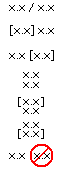
The Display Options box specifies how to display or suppress leading and trailing zeros and the method for displaying basic dimensions.
 Zero tolerance
-
Used when a linear tolerance value is true zero. Selects how zero values are displayed in tolerances. Choose Full Display, No Trailing Zeros, No Trailing Zeros - No Sign, or Suppress Display
 Zero arc minutes/seconds
-
Used when the arc minutes or arc seconds are true zero for primary units and tolerance units. Choose to show zero values for arc minutes and arc seconds for arcs or hide zero values for arc minutes and arc seconds.
 Basic dimension display
-
Shows prefix/suffix inside or prefix/suffix outside the Basic dimension bounding box.
The Primary Units box specifies precision, and display preferences for primary unit tolerances.
- Linear Precision
-
Sets the precision for linear dimension tolerances. Click the arrow and select the number of decimal places to display.
- Angular Precision
-
Sets the precision for angular dimension tolerances. Click the arrow and select the number of decimal places to display.
- Included Zeros
-
Select the check box to display a zero before fractional inch values less than one. For example, 1’ - 0 1/2”.
- Leading/Trailing Zeros
-
Select the check box to show leading and trailing zeroes on tolerance values according to the precision setting.
The Alternate Units box specifies precision, and display preferences for alternate unit tolerances.
- Precision
-
Sets the precision for alternate unit tolerance. Click the arrow and select the number of decimal places to display.
- Leading/Trailing zero
-
Select the check box to show leading and trailing zeroes in alternate unit tolerances according to the precision setting.
Options
The Options tab sets preferences for arrowhead placement, extension line visibility, radius, horizontal, and angular dimensions, and leaders and origins of ordinate dimensions.
- Arrowhead Placement
-
When creating dimensions, specifies inside or outside placement for linear, angular, diameter, and radial dimensions.
- Hide Extension Lines
-
Select the check boxes to specify to hide linear or angular extension lines.
- Radius Dimensions
-
Select a check box to specify no leader or leader from center and no jogged leader or a jogged leader.
- Diameter Dimensions
-
Shows or hides the diameter symbol when a diametric dimension is placed on a geometric circle.
Specifies no leader or a leader from the center of a circle.
Specifies a single or dual dimension line.
- Angular Dimensions
-
Specifies whether to use a quadrant or ignore a quadrant when placing text for angular dimensions.
- For a quadrant, the angular dimension changes to match the destination quadrant. The angular extension lines change to show which quadrant the angle is measuring.
- When not using the quadrant, the angular dimension text remains constant, matching the original angle when it was placed.
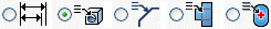
- Ordinate Dimension Leaders
-
Jogging specifies broken or straight leaders.
Alignment Select the check box to use continuous running leaders. Clear the check box to select aligned leaders or non-aligned leaders.
- Ordinate Dimension Origins
-

 Displays or hides the direction arrow.
 Displays positive dimensions in both directions.
 Select the origin indicator check box to use the origin indicator.
Select the Hide Origin Indicator check box to hide the origin symbol or clear the check box to display it.
Origin Selects an origin mark for the Countinous Running ordinate dimension sets.Note: When you change the origin mark in the style, all existing By Style origin marks in the drawing respect the new setting.
Notes and Leaders
The Notes and Leaders tab formats hole and thread notes, revision tags, hole tags, leader text objects, and chamfer notes. Inventor also has bend notes and punch notes.
Unless indicated otherwise, all values are linked to the note. Changes to the values affect notes associated with the modified style.
-
-
Selects the note type to edit its settings. Available options depend on the selected note type.
- Hole type
-
Selects the hole type. Click the arrow, and then select the hole type from the list. Available for hole note only.
Note: Set the attributes for each hole type that are in the drawing. - Edit window
-
Sets up the content of the notes. In Values and Symbols, click a value or symbol to add the corresponding property to the note text. Click the arrow next to the Insert Symbol command to select and insert a symbol.
You can use a combination of text, inserted symbols, and variables to configure the annotation text of the note. For example:
C <DIST1> X <DIST2> would result in C 10 X 10
- Options
-
Use Default sets hole note formatting to the default. Check the box to use defaults. Remove the check mark to change the formatting. Not available for chamfer and (in Inventor) bend notes.
Tap Drill indicates that the current format selected (from the combination of Hole type and Thread type) is used when the Tap Drill option is turned on for edited hole notes. Select a hole note, right-click, and select Edit Hole Note. Then select the Tap Drill option on the Hole Note edit dialog box. Not available for chamfer and (in Inventor) bend notes.
Part Units sets the note to use the measurement units of the model. Check the box to use model units. Remove the check mark to use the measurement units specified by the dimension style. Not available for chamfer notes.
Precision/Tolerance Settings opens the Precision and Tolerance dialog box so you can add tolerance information to values included in notes.
Apply to All applies all selected settings in the Options box to all hole and thread types, including all settings in the Precision and Tolerance dialog box. Not available for chamfer notes.
- Values and Symbols
-
Hole notes: Adds values and symbols to hole notes. Click a value or symbol to add it to the hole note. To remove, place the cursor after the value or symbol in the Edit Window and backspace.
 Selects a symbol from the list to adds it to the hole note.
Icon Formula Name Origin / Column in Threads.xls 
<HDIA> Hole Diameter Value
Size 
<HDPT> Hole Depth Value
Model 
<CBDIA> Counterbore/Spotface Value
Model 
<CBDPT> Counterbore/Spotface Depth Value
Model 
<CSDIA> Countersink Diameter Value
Model 
<CSANG> Countersink Angle Value
Model 
<CSDPT> Countersink Depth Value
Model 
<QTYNOTE> Quantity Note adds text to indicate quantity. Not displayed if the hole note is used inside a hole table or if the quantity is less than two.
Format defined by 

<THRP> Thread Designation Value
Thread Designation 
<THDCD> Custom Designation Value
Custom Thread Designation 
<THDPT> Thread Pitch Value
Pitch Dia 
<THRC> Thread Class Value
Class 
<THRD> Thread Depth Value
Model 
<TDDIA> Tap Drill Diameter Value
Tap Drill 
<FST> Fastener Type Value
Model (Clearance holes only) 
<FSZ> Fastener Size Value
Model (Clearance holes only) 
<FIT> Fastener Fit Value
Model (Clearance holes only)
- Chamfer notes:
-
Adds values and symbols to chamfer notes.
 Inserts the Distance1 variable (<DIST1>) in the text window.
 Inserts the Distance2 variable (<DIST2>) in the text window.
 Inserts the Angle variable (<ANGL>) in the text window. The calculated angle is always the acute angle between the selected chamfer edge and the reference edge (less than 90 degrees).
Selects a symbol from the list to add to the chamfer note.
Inserts the Angle variable (<ANGL>) in the text window. The calculated angle is always the acute angle between the selected chamfer edge and the reference edge (less than 90 degrees).
Selects a symbol from the list to add to the chamfer note.
- Bend notes:
-
Adds values and symbols to bend notes.
 Inserts the Bend Direction parameter in the text window.
 Inserts the Bend Angle parameter in the text window.
 Inserts the Bend Radius parameter in the text window.
 Inserts the KFactor parameter in the text window.
Selects a symbol from the list to add to the bend note.
Inserts the KFactor parameter in the text window.
Selects a symbol from the list to add to the bend note.
- Punch notes:
-
Adds values and symbols to punch notes.
 Inserts the Punch ID parameter in the text field.
 Inserts the Punch Direction parameter in the text field.
 Inserts the Punch Angle parameter in the text field.
 Inserts the Punch Depth parameter in the text field.
 Inserts the Quantity Note property in the text field.
Selects a symbol from the list to add to the punch note.
Inserts the Quantity Note property in the text field.
Selects a symbol from the list to add to the punch note.
- General settings
-
Unlike other options, general settings are a single setting for each hole note or leader object.
Edit Quantity Note opens the Quantity Note dialog box. Allows custom configuration of the quantity note display in the context of a hole note (represented by the Quantity Note symbol).
Leader style sets a specific leader for hole notes and leader text.
Edit opens the Leader Style so that attributes can be modified. For more information about the leader style, see Style and Standard Editor - Leader Style.
Justify text to leader overrides the text style justification settings and automatically justify toward the leader. Clear the check box to retain the text style.
Leader orientation specifies whether leader text is aligned to the leader or horizontal to the line. Click the arrow to select horizontal or aligned.
Leader text alignment controls how text displays relative to the leader landing line and sets underlining for multi-line text. Click arrow to select first line centered, all above landing line, first above landing line, JIS alignment/format, vertical extension, or all above landing underlined.
- Thread Note Settings
-
Select the Custom Designation check box to apply the custom thread designation field from the Thread.xls spreadsheet instead of the default note (thread designation and class).
For more about Thread data and custom notes see To Work With the Thread Data Spreadsheet.