Describes section view settings, how to constrain and align these views, and how to control their appearance.
You can create a section view by drawing a line that defines where to cut the section or by specifying a line in a drawing sketch that is associated with the parent view.
A view cutting line knows what types of views can be projected from it. Depending on how the line was created, it can define the type of section view or define a boundary for a partial view.
The length of the cutting line defines the extent of the section view. A cutting line that passes only partially through the model view results in a partial section view.
A view cutting line outside the parent view defines a plane from which to project an auxiliary view.
When creating a child (dependent) view, the section attributes of the parent view are copied to the child view, but they are not associative. Section view attributes changed on the parent do not affect the child. You can modify the settings without affecting the parent view attributes.
Section and visibility settings are copied to projected views. All views provide independent control of section and visibility settings. Changes to settings only affect the view where the changes of the contents settings are made. The section and visibility settings of a view also affect the results of a breakout view operation.
The Section View Preview as Uncut option, in the Drawing tab in Application Options, displays the preview of the section view as uncut. This controls the preview of the model and improves the performance of the previews of section views.
Constraining and Aligning Section Views
As you draw a view cutting line, constraints to features and edges are inferred as you move the cursor. If you place a point while an inference line is displayed, the constraint is automatically applied.
A view defined by a view cutting line is usually aligned to the parent view. It can be moved within the alignment constraint. If you remove the alignment, the view can be moved freely in the drawing, and the view cutting line with its arrowheads and text label are displayed on the parent view.
If you used inferred or explicit constraints to place the view cutting line, you must edit the sketch to remove the constraints before you can drag the constrained points or line segments.
Hatching in Section Views
Hatch patterns are automatically applied to section views when you create them. The active Hatch style defines the pattern, scale, shift, and other attributes of the hatch.
When multiple parts are cut in a section view, a specific hatch angle is applied to each section hatch. Default Section Hatch Angles are specified by Preset Values on the General tab of the Standard style pane. The final hatch rotation for cut views also includes the rotation angle defined in the Hatch style.
Note: The default hatch rotation angles apply when you create section views. If the setting in the Standard changes, existing section views keep the hatch rotation angle as an object override.

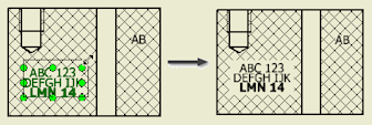
The Cross Hatch Clipping option on the Drawing tab of the Document Settings dialog to break hatching around drawing annotations in cut views.
To enable clipping around user-defined symbols, select the Symbol Clipping option for individual symbol instances. The cross hatch clipping is not supported for datum targets and in isometric views.

Change Inheritance of the Section and Breakout Cut
Isometric projected views created for section views inherit the section cut by default. Orthographic projected and auxiliary views support the inheritance of the section, but it is switched off by default.
Isometric projected views created for views with a breakout inherit the breakout cut by default. Orthographic projected and auxiliary views do not support inheritance of breakout operations.
Slice Operations in Section Views
You can create a section view with some sliced components and some sectioned components depending on their browser attribute settings.
You can optionally choose to override browser component settings and slice all parts in the view according to the section line geometry. Components that are not crossed by the section line do not participate in the slice operation.
Specifying Section View Appearance
 Shows hidden lines.
 Removes hidden lines.
-
 Specifies shaded rendering.