How to control the alignment and depth of a section view, and how to include a slice operation.
What's New: 2021.1
You can define the view cutting line while Section View is active or create sketch geometry to use for the view cutting line. You can also edit the depth of an existing Section View, and include or exclude a Slice operation in the view.
When creating section views of presentations with trails, the trail is visible in the drawing view. If appropriate, right-click a view or a single trail and select Show Trails to turn trails on or off.
- Projected creates the projected view from the sketch line. This option is set as default if all segments are exactly 90 degrees.
- Aligned results in section view perpendicular to the line of projection. Body cut lines do not display in the resulting view. The aligned option is not available for a child (dependent) view, and is only available when Include Slice option is checked.
Override Section View Alignment During Placement
When creating a section view, by default, the view is aligned with the parent view. You can use any of the following methods to enable/disable alignment with the orthographic projection from the base view. When you disable alignment, you can align the section view with any other view because it is no longer aligned to the parent view.
- Create the section view, but do not click to place it.
- As you drag the section view away from the parent view, use one of the following methods to disable alignment:
-
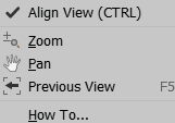
- Context menu
Right-click in the graphics window. and deselect Align View.
-
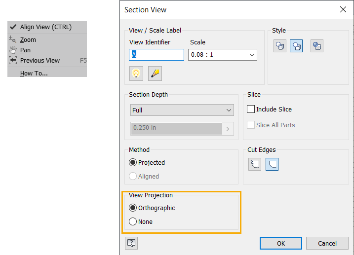
Section View dialog box
Under View Projection, select None.
-
Hold down the CTRL key
Click to place the section view where you want it and then release the CTRL key.
- Context menu
Create a Section View Defined by Sketch Geometry or an Aligned View
For an aligned section view, when you either sketch a multi-segment section line or select a view sketch containing a multi-segment section line, you can specify the method of the section view, projected, or aligned. If one or more segment angles are non-perpendicular, the default method is set to Aligned. If all segment angles are exactly 90 degrees, the default method is set to Projected.
You can use an unconsumed model sketch as a section line.
- Select an existing view to use as the parent view.
- On the ribbon, click
Place Views tab
 Create panel
Section
Create panel
Section
 .
.
- Select the view cutting line you defined in the sketch.
- (Optional) Specify the appearance of the view in the Section View dialog box.
- For a section view defined by sketch geometry:
- Edit the View Identifier and select the Scale.
- Select the Toggle Label Visibility icon to change the label visibility.
- Click Edit View Label to edit the view label in the Format Text dialog.
- Set the display Style and Section Depth for the view.
- Specify whether the Method of the section view is projected or aligned.
- Select the desired Cut Edges to display Jagged or Smooth cut lines in the section view.
- For an aligned section view:
- Specify the label, scale, display style, and section depth for the view.
- In the Method area, to specify the preferred projected method, select the section view, right-click, and select Edit Section Properties.
- For a section view defined by sketch geometry:
- Move the preview to the appropriate location and click to place the view. You can place the view only within the alignment indicated by the view cutting line.
Create a Slice Operation with a Section View
- Select an existing view to use as the parent view.
- Click to set the start point for the view cutting line, and then click to place extra points for the line. The number and location of points on the view cutting line determine the type of section view.
- Right-click, and then select Continue to complete the view cutting line.
- In the dialog, set the label, scale, display style, and section depth for the view.
- Make sure that Include Slice is checked.
- (Optional) Check Slice All parts.
- Move the preview to the appropriate location, and then click to place the view. You can place the view only within the alignment indicated by the view cutting line.
Edit Section View Definition or Type
- Do any of the following:
- Drag a point to shorten or lengthen a line segment.
- Drag a line segment to move it, and shorten or lengthen adjoining line segments.
- Drag an arrowhead to change its direction or the length of the landing.
- Drag a point to change the angle of a line segment.
Change the Depth of a Section View
- Right-click the section view or cutting line.
- Select Edit Section Properties from the context menu.
- Change the section depth settings in the dialog:
- In the Depth Control, select Full to create the section view to all geometry beyond the cutting line.
- Select Distance to specify a distance of viewing in model units beginning from the cutting line, and enter the depth distance in the Distance field.
Note: Setting the section depth to zero reverts to the smallest available section depth. Not a true zero-depth section. The actual value is 0.000012.
Include or Exclude a Slice Operation in an Existing Section View
The Include Slice option creates a section view, with some components sliced and some components sectioned, depending on the Browser attribute settings. If you are using Inventor, the optional Slice All parts overrides Browser component settings and slices all parts in the view according to the Section line geometry. Components not crossed by the Section Line, do not participate in the Slice operation. This view is essentially a true zero-depth, so the Section Depth fields are dimmed when this option is checked.
- Do one of the following:
- Select Include Slice to include a slice operation.
- Clear Include Slice to exclude a slice operation.
- (Optional) If you select Include Slice, check Slice All Parts to include all parts.
Change Inheritance of the Section or Breakout Cut
- Right-click the view and select Edit View.
- Open the Display Options tab of the Drawing View dialog, and select the appropriate options in the Cut Inheritance section.