Add balloons to drawing views

What's New: 2022

If you create a parts list before adding balloons, the balloons use properties specified by the parts list. If the view does not have an associated parts list, the BOM Properties dialog box opens so you can set the properties.

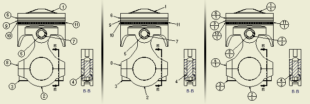
The following image shows how balloons update per changes to balloon properties.

Add balloons to individual parts

  1. On the ribbon, click Annotate tab Table panel Balloon.
  2. In the graphic window, select component geometry to attach the balloon to.
    Tip: Right-click, and select the Single-Segment Leader option to place balloons with a single leader segment. Then skip steps 4 and 5 in this procedure. The setting is saved in the computer registry and is retained until you change it.
  3. Move the cursor, and click to add a leader vertex.

    Hold the CTRL key on your keyboard to enable leader line snapping in 15° steps.

  4. Repeat the previous step until the balloon is in the appropriate position.
  5. Right-click, and click Continue.
  6. Continue placing balloons. When you finish, right-click, and click Cancel.

If a parts list is not created in the drawing or for a selection, the BOM Properties dialog appears. You can specify the BOM view during the balloon command. The balloon command continues only after properties are specified.

Use the following procedure to create balloons before a parts list:

  1. On the ribbon, click Annotate tab Table panel Balloon .
  2. In the graphic window, select view geometry to set the start point for the leader line. The BOM Properties dialog box is displayed.
  3. In the BOM Properties dialog box, select the BOM Settings:
    • Select the appropriate BOM view.
    • If the BOM view was not enabled in the assembly, you can enable the BOM view and set the desired properties.
  4. Click OK to close the BOM Properties dialog box.
  5. Move the cursor, and then click to add a vertex for the balloon leader.
  6. When the symbol indicator is in the appropriate position, right-click, and then select Continue to place the symbol.
Note: After you set the BOM Settings in the BOM Properties dialog box, all balloons and parts lists created for the same source respect this setting.

Automatically add balloons to multiple parts

Use Auto Balloon to create multiple item balloons for selected components in drawing views.

Note: Auto Balloon cannot be used for raster drawing views.
  1. On the ribbon, click Annotate tab Table panel Auto Balloon .
  2. Browse to a file or select the view to identify the BOM source in the graphics or the browser.
  3. Specify components to balloon by selection in the graphics or browser contents.
    Note: Auto Balloon supports Window select and Shift to remove.Right-click and choose Select All from the menu to select all components for the view.
  4. For balloon placement, set the appropriate options and specify the balloon placement.
  5. Click OK or Apply to create the balloons.
Note: To add balloons for subassembly components in a view with a nested parts list, right-click the view in the browser, and then select Show Contents before clicking Balloon.

Attach a balloon for another part to an existing balloon

  1. Right-click an existing balloon, and select Attach Balloon from the menu.
  2. Select a part in the view to specify the balloon to attach.
  3. The new balloon is automatically attached to the existing balloon.

Attach balloons from list

  1. Right-click a balloon in the drawing and select Attach Balloon From List.
  2. In the Attach Balloon dialog box, click the arrow on the Filter list and select the parts to display in the list.
  3. In the table, select parts for which you want to create and attach a balloon.

    If appropriate, right-click in the table and choose an option: Select All, Clear All, or Invert Selection (to select all unselected parts or clear the selection of all selected parts).

  4. When parts are selected, click OK. Balloons are attached automatically.
Note: Balloons are attached vertically by default. To change the orientation of the multi-item balloon, drag a grip point of an attached balloon to the horizontal position.

Create a balloon for a custom or virtual part

If you have a virtual part in the assembly, or a custom part defined in the parts list, you can create a balloon for it. The balloon can be attached either to a part in the drawing or to an existing balloon.

To place a new balloon:

  1. On the ribbon, click Annotate tab Table panel Balloon .
  2. In the graphics window, click to set the start point for the leader line.
  3. Move the cursor and click to add a vertex.
  4. When the symbol indicator is in the appropriate position, right-click, and choose Custom/Virtual.
  5. Right-click again, and then select Continue.
  6. In the Custom/Virtual Parts dialog, select the part, and click OK.

Continue placing balloons, right-click, and select Done to end the operation.

Display Instance Properties in Balloons

Instance properties are properties assigned to individual component instances that are stored in the parent assembly. Unlike iProperties, instance properties don't affect the referenced component files. Balloons display instance properties values when the style of the balloons contains the name of the instance property. To learn how to display instance properties in balloons, see To Work with Instance Properties.