About formatting and customizing the annotation tags for items in a parts list.
After you create a drawing view, you can add balloons to the parts and subassemblies in that view. The number in the balloon corresponds with the number of the part in the parts list.
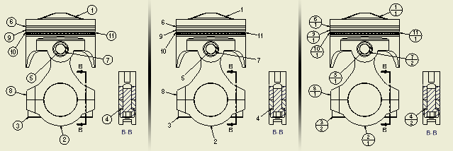
The following image shows various balloon types.

Formatting balloons
You can define a default format for balloons. Use the Style and Standard Editor dialog box to set the balloon style.
If you prefer a different style for a specific balloon, you can modify the style definition after you place the balloon in the drawing. The modified style is saved in the current document only. To override the style library balloon definition with the new one, right-click the balloon style type in the Style and Standard Editor, and then select Save to Styles Library.
Customizing existing balloons
You can modify the settings for a balloon after you place it in the drawing. Right-click the balloon, and then perform the following operations:
- Change the balloon style.
- Change the balloon type and contents.
- Attach another balloon.
- Change the arrowhead or add a vertex or leader.
A balloon formatted with the standard-defined balloon style can be updated by changing the active Object Default style in the Style and Standard Editor dialog box. All balloons using the By Standard style are updated with changes made to the active Object Default style.
Modifying balloons
You can edit a balloon to override the balloon shape, or to edit or override the value displayed in the balloon.
- Balloon text
- Balloon shapes
- Leader lines
- Arrowheads
- Text and geometry of attached balloons
- All edits in parts lists associated with the same source as a balloon are reflected in the corresponding balloon (until you create an override for the balloon value). Also all edits in balloons are reflected in related parts lists.
- Changes made in the Override column in the Edit Balloon dialog box are not reflected in the parts list.
Creating a balloon for a custom or virtual part
If you have a virtual part defined in the assembly, or a custom part defined in the parts list, you can create a balloon for it. The balloon can be attached either to a part in the drawing or to an existing balloon.
Aligning multiple balloons
You can select multiple balloons in your drawing, and align them horizontally, vertically, or parallel to a model edge. After you start a balloon alignment command, aligned balloons are previewed, and you can place them to the desired position in the drawing view.
The original offset of the balloons is kept as follows: Horizontally aligned balloons are moved along the vertical axis, and their original horizontal distance is kept. Vertically aligned balloons are moved along the horizontal axis, and their original vertical distance is kept. Balloons aligned to an edge are moved in direction perpendicular to the reference edge, and their original offset parallel the edge is kept.
To avoid overlapping and to keep a specific distance between balloons, use the Vertical Offset and Horizontal Offset commands. To set the offset distance between balloons, in the current balloon style, edit the Default Offset value. If you set the Default Offset value to zero, there is no offset, and the balloons are aligned tangent to one another.
Moving and placing multiple balloons and leaders
You can drag them to a new location. If Autodesk Inventor detects a mix of leader types with the balloons (such as multiple and single vertex types), all leaders are "rubberbanded" from the arrowhead as if they are single vertex leaders.
To place multiple balloons, select a view or preselect components in a view.