Set up parameters for complete transmission layout.
|
Access: |
Ribbon:
Design tab
 Power Transmission panel
Synchronous Belts
Power Transmission panel
Synchronous Belts
|
|
Belt |
|
|
Specifies a synchronous belt type you select from a library. To display the library, click the arrow next to the Belt edit field. The library is comprised of files stored in the ...Design Data\Design Accelerator\Tables\S-Belts\ folder. Click the synchronous belt type and the type is entered to the edit field. The width of the selected belt may be specified manually or designed by performed analysis. |
|
|
Available sizes of each belt are described by its XML file. As the same type and size of the belt from different producers can have different power capacity, you can modify maximum allowable belt tension on the calculation page of the dialog box. Resultant belt power rating is related to the current transmission layout and maximum allowable belt tension. By creating a belt XML you might define your own belts from a particular supplier. |
|
|
Belt Mid Plane |
Specifies the main belt plane. You can select a planar face or work plane. To adjust the mid plane root point of the selected plane, use Mid Plane Offset. You can also use the active coordinate system icon to adjust the X or Y axis direction and the coordinate origin point. |
|
Belt Width |
The available belt widths are based on the selected belt. Select the belt width manually or let the generator advise the minimum belt width based on analysis performed. The generator automatically modifies the width of each standard pulley within the pulleys' list. If a pulley is marked green as a custom size pulley, then you must modify manually all pulley properties as and pulley width. |
|
Number of Teeth |
Use the list to select number of teeth. According to your selection, generator sets the belt length (move sliding pulley accordingly) even if the belt length is currently locked (Lock belts length on/off option within the More Options area). The Lock belts length on/off option locks the belt length for assembly update and dragging pulleys within the Autodesk Inventor window. This prevents you from an unexpected change of the belt length but you can still to select an appropriate belt length. |
|
Pulleys |
|
|
Adds any number of pulleys. Each pulley is represented as one line of controls within the list. To reorder pulleys in the list, drag and drop lines. |
|
|
A pulley used for belt transmission needs to match with the selected belt. A critical property is circular pitch. If the belt is changed and some existing pulleys do not match built-in criteria, such pulleys are marked with red color and you are prompted to change the pulley type. |
|
|
The minimum number of synchronous pulleys for the generator is 2. The first pulley is always the driver and has to be a synchronous pulley with teeth. It cannot be a flat pulley. Flat pulleys are considered as idlers only and they cannot transmit any load. Power ratio for all flat pulleys is always 0.0. There has to be at least two synchronous teethed pulleys within transmission. At least one of the pulleys has to be sliding or sliding with a controlled position. |
|
|
There are 3 options that define what action should be performed to a pulley: |
|
|
|
Component Inserts a pulley as a component. Use this option to create new part document of the pulley. The application uses predefined template files for pulleys and belts. You can add additional features into pulley documents. The file name can be selected within the Properties dialog box. |
|
|
Existing Selects an existing pulley within the assembly. Use this option if the pulley that should belong to the belt transmission already exists within the assembly. The selection differs if a flat or synchronous pulley is selected. If an existing synchronous pulley is selected, the selection of a part circular pattern is required. The pattern is used to determine the number of teeth and it is considered to be an input parameter that is taken from the existing pulley. Also the pattern axis defines pulley position. If an existing flat pulley is selected, the cylindrical face is required that defines flat pulley diameter and pulley axis. |
|
|
Virtual Does not insert a pulley into the assembly. This option is similar to the Component option; however, no component is created within the assembly. Use this option if it is not clear what pulley component is used in the assembly. No BOM information is created within the assembly. |
|
Pulley placement types |
|
|
Each of the pulleys has its own placement type: |
|
|
|
Fixed position by selected geometry Selection of Work Point, Work Axis, Cylindrical Face or Sketch Point is required as a geometrical condition of the pulley center. You cannot specify coordinates by precise numbers. The position is controlled automatically by projecting a center point into the belt main plane. |
|
|
Fixed position by coordinates You can drag and drop to position a pulley within the main belt plane. Also, you can specify the position by precise values of X and Y coordinates. These coordinates are related to the belt coordinate system. Double-click the pulley center grip to display the Pulley's X, Y coordinates dialog box. |
|
|
Free sliding position The exact pulley center is adjusted to accomplish the belt length condition. The pulley center is specified by a specific point and a specific vector. The closest belt length is selected for actual specific point. The exact pulley center is then moved along the specific vector until the belt length condition is accomplished. Direction of specific vector is determined automatically by the application and cannot be changed. You cannot specify coordinates by exact values or expressions. |
|
|
Controlled sliding position Similar to the free sliding position placement. The direction of a specific vector is controlled by selected geometry. Select the Work Axis, Work Plane or Planar Face that needs to be perpendicular to belt plane. You can adjust the specific point only by drag and drop. The generator automatically selects the closest belt length and calculates the exact center pulley position to accomplish the belt length condition. You cannot specify coordinates by exact values or expressions. |
|
|
Rotation driven sliding position Position of the sprocket is determined by Synchronous Belt Generator with respect to the center of rotation and given arm radius. Use the angle grip to move the sprocket or pulley to the appropriate location. Generator automatically advises correct rotation based on a belt or chain length. Center of rotation is defined by selected geometry reference. |
|
Each of the pulleys is editable: |
|
|
|
Pulley Properties Displays the Pulley Properties dialog box where you can change pulley parameters (diameter, depth, fillet radii, power ratio and so on). |
|
You can modify pulley properties such as position and size of pulleys by using Drag and drop grips within graphical window. Modification of pulley center position is described above. By default, the size of the pulley can be changed only along with standard (recommended) values. Use SHIFT + drag pulley size grip to set a non-standard size of the pulley. Use CTRL + drag origin pulley grip for a smooth drag of any pulley without any unexpected change. If you release the CTRL or mouse button, the trajectory is updated. |
|
|
|
Delete Deletes the pulley. |
|
|
Browse for pulley type Displays a dialog box where you can select from filtered pulleys. |

|
|
|
|
Displays additional options for synchronous belts design. To display the More Options area, click |
|
|
|
Use the on/off command to hide or show belt drive coordinate system icon within graphics screen of your assembly. The active coordinate system icon lets you adjust X or Y axis of the belt coordinate system as well as the system origin point. |
|
|
Click to lock belt length. If this option is switched on, the belt length is kept as constant value and can only be adjusted manually in the dialog box. If a new pulley is added or removed, or if the pulley position or size changes, the belt length remains the same and tightening pulley position is adjusted accordingly. |
|
If this option is switched off, the generator automatically selects the closest belt length that fits into the current pulley positions. Then sliding pulley position is adjusted accordingly. This option allows the minimum change in tightening pulley position. |
|
|
You can drag the sliding pulley using center grip. If the lock belt length option is switched off, you can change belt length by dragging any pulley. The position of the sliding pulley is always consistent with belt length criteria. |
|
|
By default this option is switched off. |
|
 (More)
|
Create Belt as |
Select how the belt geometry is interpreted in the assembly. |
|
|
|
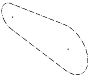
Sketch creates belt as a simple sketch with dash-dot line type. Pitch diameters are used to generate the profile. |
|
|
|
Solid creates simple solid without belt teeth. |
|
|
|
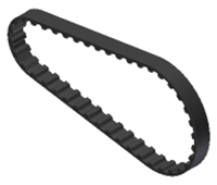
Detailed creates belt as a complete solid including all teeth. |
|

|
Adjust Timing |
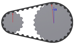
By default, the pulley timing is switched off. Pulley timing is computed automatically based on a driving pulley position. Check the Adjust Timing box to adjust timing manually. Initial rotation of each gear has to be determined to engage belt teeth with pulley tooth gaps successfully as shown in the following image. The initial rotation of the pulleys is based on exact pulleys position as well as their size. The entire system has only one degree of freedom and can be constrained.
To adjust pulley timing, you must choose a pulley with fixed timing constraint first. Then, select timing reference geometry (linear entity parallel with main belt plane or planar entity perpendicular to main belt plane). All other pulleys within the belt drive automatically adjust their rotation to engage with the belt teeth. Flip comamnd reverts direction vector of reference geometry. Additionally, you can adjust initial rotation of each teethed pulley using tooth grip as shown in the following image. The first tooth in the pattern is displayed and pulley can be rotated with respect of belt pitch.
Use the graphical preview to view the pulley timing. |

|
Summary of Messages |
|
Displays the reports about calculation. To open the Summary of Messages area at the bottom of the Calculation and Design tabs, double-click the double line at the bottom of tabs or click the chevron at the bottom of the tabs. |
|
Graphical Preview |
|
A graphic preview of the selected geometry is displayed in Autodesk Inventor. You can use grips to modify individual pulley size and position. Belt length is automatically determined and sliding pulley position is updated accordingly based on available standard belt length. |
Flat Pulley Properties dialog box