Attach a text note to a specific view or geometry, adjusting the format of text, measurement, and leader.
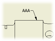 |
Use Leader Text to add notes with leader lines to a drawing. If you attach a note leader line to a view or to geometry within a view, the note is moved or deleted when the view is moved or deleted. |
Add a note with a leader
|
|
|

Edit leader text
You can edit the text or change the symbols or parameters in the note.
- Select the leader text, right-click, and then choose Edit Leader Text from the menu.
- In the Format Text dialog box, click in the text box to set the insertion point. You delete or add text, or use the options on the dialog box to add symbols and named parameters or change the text formatting.
Change the unit attributes of leader text

You can set leader text to display parameters in dual measurement units. They display in the units specified in the associated drafting standard and in the defined alternate units.
- Select the leader text, right-click, and then choose Edit Unit Attributes from the menu.
- Click to remove the check from the Use Standards Notation check box.
- Set the attributes.
Edit arrowhead
You can change termination symbol for the leader line.
- Select the leader text, right-click, and choose Edit Arrowhead from the menu.
- In the Change Arrowhead dialog box, click the arrow, and choose the terminator from the list.
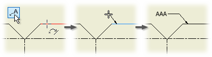
Add a vertex to the leader line
You can add points to the leader line and drag the points to define additional vertices for the line.
- Select the leader text, right-click, and then choose Add Vertex/Leader from the menu.
- Move the cursor over the line, and then click to place the new point.
- Click the new point and drag it to the desired location.
Change the style while creating leader text
On the Annotate tab, Format panel, click the arrow on the Style list, and then select a style.
Change the style of the existing leader text
Select the leader text to change and then, on the Annotate tab, Format panel, click the arrow on the Style list, and then select a style.
Display instance properties as leader notes
Instance properties are properties assigned to individual component instances that are stored in the parent assembly. Unlike iProperties, instance properties don't affect the referenced component files. Instance property values have a higher priority than the values of custom iProperties. When a custom iProperty exists and you create an instance property of the same name, instance property covers the custom iProperty. To learn how to display instance properties as leader notes, see To Work with Instance Properties.