Insert Associative DWG geometry, manage layer visibility, and create 3D models of 2D layouts.
What's New: 2020.2
Create 3D Inventor parts or assemblies associative to the source 2D geometry created in AutoCAD:
- The 3D part or assembly created in Inventor associatively updates when the 2D geometry changes in AutoCAD.
- The location of a DWG underlay associatively updates when the location of the DWG Underlay's plane or insertion point changes. For example, if you place a DWG underlay on the corner of a model, and then change the location of the corner of the model, the location of the DWG underlay updates associatively. The changes you make with the Translate command are associative.
- Use the Project DWG Geometry command to project DWG geometry, polylines, open or closed loops, and DWG blocks, and then use the projected sketch elements to create modeling features. 3D Inventor models based on the DWG geometry updates when the 2D geometry changes in AutoCAD.
Browser status icons
 The DWG Underlay is associative to the model.
 The DWG Underlay is not associative to the model.
To insert an AutoCAD DWG file as an Associative DWG
After importing or placing an AutoCAD DWG into a part or assembly file, you can create sketches by referring to the DWG geometry.
-
Manage tab
 Insert panel
Import
Insert panel
Import
Optionally, 3D Model tab
Create panel
Import
- In the Import dialog box, select the DWG and click Open.
In Assemblies
- Assemble tab
Component panel
Place
- In the Place Component dialog box, select a DWG file and click Open.
- Select a plane, planar face, a sketch, or a sketch curve. Selecting a sketch or sketch curve places the DWG on the same plane/face as the sketch.
- Specify the origin by selecting a point on the selected plane. Select one of the following points as the insertion point to make the DWG associative:
- 2d Sketch point, start/center/end point of 2d sketch curves
- Start/center/end point of edges
- Points on a face
- Work point
- Vertex
DWG is placed in, by mapping the XY(+z) of the DWG with selected plane, and mapping the Origin point of DWG with specified point. The inserted associative DWG underlay displays in the browser
.
To change the insertion point of a DWG Underlay in a part
Use Translate to change the insertion point of the origin point of a DWG underlay by moving, rotating, or snapping on to a located plane.
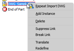
- Right-click on the DWG file in the browser and select Translate from the context menu.
A triad displays on the existing origin point of the DWG file.
- Use one of the following methods to change the insertion point and maintain the associativity to the model:
- Select Locate to move the triad and specify a new origin point on the DWG.
- Click the drop-down arrow and select Locate to Origin to select the DWG origin as the new origin point.
- Select Snap to to move the triad by picking an existing point on the model.
- Select
Snap to to define a new rotation angle: First rotate to define a new angle, and then redefine the origin point using Snap To. The DWG is moved parallel to the snapped point and keep the new rotation angle.
Important: Drag the rotation handle before selecting Snap To. Dragging the rotation handle after snapping to the new point, removes the associativity between the DWG Underlay insertion point and the model.
Important: Dragging the rotation handle when Locate is active removes the associativity between the DWG Underlay insertion point and the model.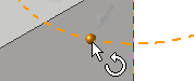 . To define a new rotation angle and maintain associativity you must use the
Snap To command. If you rotate the angle when
Locate is active, the associativity to the DWG underlay is removed and the DWG icon in the browser changes to reflect the nonassociative status
.
. To define a new rotation angle and maintain associativity you must use the
Snap To command. If you rotate the angle when
Locate is active, the associativity to the DWG underlay is removed and the DWG icon in the browser changes to reflect the nonassociative status
.
The DWG geometry is moved to the newly defined insertion point with the selected point.
- Select OK to complete the operation
 .
.
To remove the association between the DWG Underlay and the original DWG
Use Break Link to remove the association between the imported DWG file and the original DWG file.
- In the browser or graphic window, right-click on the imported file, and select Break Link from the context menu.
To manage layer visibility
- Right-click on the DWG file in the browser and select Layer Visibility from the context menu.
- The Layer Visibility dialog box provides controls to manage layer visibility:
- Select All button turns on all layers
- Clear All button deselects all layers.
- Invert Select inverts the selection.
You can also manually select and deselect the checkboxes to manage layer visibility.
To turn on or off the entire DWG graphics visibility: Right-click on the DWG file in the browser and select Visibility from the context menu.
To change and re-establish the associative plane and origin point in a part
- Use the
Redefine browser context menu option to:
- Move the DWG underlay to a different associative plane and origin point.
- Reconnect the DWG Underlay's plane/point of associativity if the dependent plane and origin point are deleted.
- Re-establish associativity with legacy files: The associativity that exists in a legacy DWG Underlay Inventor part or assembly may not be maintained when you open the file. Use the Redefine command to re-establish the associativity.
- Right-click on the DWG file in the browser and select Redefine from the context menu.
- Select a plane, planar face, a sketch, or a sketch curve to place the DWG and then select the origin.
To crop DWG underlay geometry
- Right-click on the DWG file in the browser and select Crop from the context menu.
- Click in the graphics and select an area you want to keep.
- Right-click in the graphics window, and drag a window around the area you want to keep.
- Select OK to complete the crop. Any geometry not included in the selected area is removed.
- To remove the crop and restore the cropped geometry: In the browser, expand the DWG icon. Right-click on the crop icon
 and select delete.
Underlay geometry cropped in a part or assembly file displays as cropped geometry in a drawing view of the file.