You can create a shell with uniform or unique thickness.
The Draft feature applies a taper to part faces to cant a surface or allow a part to be extracted from a mold. Draft is defined by specified faces, pull direction, angle, and fixed edge or tangent surface. You can create three types of drafts in Inventor: Fixed Edge, Fixed Plane, or Parting Line.
To begin, create a 3D part with faces or edges to draft.
Create a Shell
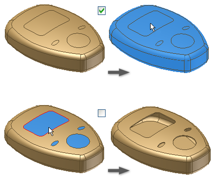
The Shell feature removes material from a part interior, creating a hollow cavity with walls of a specified thickness. Selected faces can be removed to form a shell opening.
- Click
3D Model tab
 Modify panel
Shell
Modify panel
Shell
 .
.
- Using the Remove Faces selector in the Shell tab of the Shell dialog box, select the faces to you want to remove in the graphics window. Part surfaces that are not selected for removal become shell walls.
- To aid in your selection, turn Automatic Face Chain on or off.
If selected, Automatic Face Chain enables the automatic selection of multiple tangent continuous faces. It is selected by default. Clear the check box to allow individual tangent face selection.
- If available in a multi-body part file, click Solids and choose the participating solids.
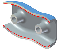
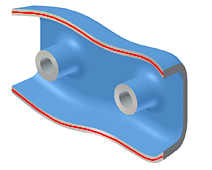
- Specify the direction of the shell boundary relative to the part face:
- Inside. Offsets the shell wall to the part interior. The external wall of the original part becomes the external wall of the shell.
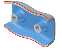
- Outside. Offsets the shell wall to the exterior of the part. The external wall of the original part is the internal wall of the shell.
- Both Sides. Offsets the shell wall equal distances to the inside and outside the part. Adds half of the shell thickness to the thickness of the part.
- Inside. Offsets the shell wall to the part interior. The external wall of the original part becomes the external wall of the shell.
- Specify the shell’s Thickness.
Thickness is applied uniformly to shell walls. To use the thickness value in a parameter table, highlight the value in the box, and then right-click to cut, copy, paste, or delete it.
- (Optional) To change the thickness of a specific shell face, click More
 , click a row in the Unique Face Thickness Table, select one or more faces, and enter a new value in the Thickness column. Continue to change face thickness, as needed.
Tip: To reset a shell face to its original thickness, delete the row.
, click a row in the Unique Face Thickness Table, select one or more faces, and enter a new value in the Thickness column. Continue to change face thickness, as needed.
Tip: To reset a shell face to its original thickness, delete the row. - (Optional) To change how approximate shelling solutions are computed, click the More tab, and select Allow Approximation. Then, select a deviation type and computation preference:
- Allow Approximation. When no precise solution exists, allows a deviation from the specified thickness while computing the shell feature. A precise solution creates a shell where each point on the original surface has a corresponding point on the shell surface. The distance between these two points is the specified thickness.
- Mean. Deviation is divided to fall both above and below the specified thickness.
- Never Too Thin. Preserves minimum thickness. The deviation must fall above the specified thickness.
- Never Too Thick. Preserves maximum thickness. The deviation must fall below the specified thickness.
- Optimized. Computes using a tolerance that allows a minimal compute time.
- Specify Tolerance. Computes using the specified tolerance. Considerable computation time can be required.
- Click OK.
- If an approximation is used, click OK in the message box to accept the results or Edit to return to the Shell dialog box More tab.
How to Create a Shell With Unique Face Thicknesses
