Placed features include fillets, chamfers, holes, threads, drafts, and shells.
What's New: 2022
Fillet

Fillets are placed features that round off or cap interior or exterior corners or features of a part.
You can create edge fillets, which are based on selected edges; face fillets between two adjacent faces or face sets; or full round fillets, which are variable-radius fillets that are tangent to three adjacent faces or face sets.
- A fillet feature can be edited, suppressed, or deleted independently of the extrusion feature, without returning to the original sketch.
- If the remaining edges are to be filleted, you have more control over the corners.
- You have more flexibility when performing subsequent operations such as applying face draft.
- Some placed feature commands have a graphic manipulator that is used to modify the feature through in-canvas interaction. The manipulators have detents that make it easy to get a commonly used value.
- It is easier to add draft to a face that intersects with other faces at a sharp angle, so it is better to add draft to a face before adding fillets.
- Fillets can increase the time required to update when feature dimensions change. To work most efficiently, add the features of the basic design early and wait until the end of the process to add features such as fillets.
- Reordering features can cause existing fillet features to produce unwanted results. Adding features such as fillets and chamfers at the end of the modeling process can minimize problems.
Chamfer

Chamfers bevel part edges. Chamfers can be equal distance from the edge, a specified distance, at an angle from an edge, or at a different distance from the edge for each face. Like fillets, they do not require sketches and are constrained to the edge on which you place them.
For chamfers created in the assembly environment, the geometry can be selected from multiple parts.
Because chamfers are finish features, consider placing them toward the end of the design process when other features are stable. For example, in assemblies chamfers are often used to remove material in preparation for subsequent operations such as welding.
Hole

The Hole feature places a specified hole in a part, optionally with thread. You can create counterbore, countersink, spotface, and drilled holes with custom thread and drill point types. You can specify a simple hole, a tapped hole, a taper tapped hole, or a clearance hole, and include thread types from the thread data sheet. You can create holes individually or in a pattern.
In the part environment, create multiple holes as a single feature using either sketched hole centers or selected endpoints or center points of geometry. You can change dimensions, hole type, termination, and other parameters for all holes at once.
If you create a single hole and duplicate it in a pattern, you define the count and spacing of the holes in the pattern. For holes in a pattern, as well as the hole characteristics, edit both the hole feature and the pattern feature.
In the part environment, use a shared sketch to create a pattern with multiple hole features and more than one hole size or type. Shared sketches are not available when creating the hole as an assembly feature.
Thread

- Threading an existing hole or extruded cut.
- Threading an extruded cylinder, such as a threaded stud.
- Threading a revolved shaft.
Predefined thread types are specified in the Thread data spreadsheet (Thread.xls), which is located by default in the Design Data folder.
In drawing views, you can add a thread note to annotate a threaded hole, shaft, or cylinder. In shaded drawing views, the threads are shown the same as in the model.
Draft
Draft is a taper that you apply to specified faces of a feature. Use Draft to cant one or more faces on a part so that you can retrieve it from a mold. When designing features for molded or cast parts, you can apply draft by specifying a positive or negative taper angle for an extrusion or sweep. To add draft to an existing feature or individual faces, use the Draft command.
When you apply draft to a face, the relationship between the pull direction and the fixed edge, face, or plane determines the result of the operation.
You select edges or axes to specify the pull direction (of the mold from the part) and the angle of the draft. The draft angle is calculated from a fixed edge (plus any tangent edges), one or more contiguous edges, or a fixed plane.
Shell
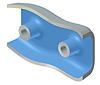
The Shell command produces a hollow part with a wall thickness you define. Shells are parametric features used for cast and molded parts. Material from the part interior is removed, leaving a hollow cavity. Changes to the dimensions of either the part or the shell automatically resize both.
By default, Autodesk Inventor provides a precise shell feature. If a precise solution does not exist and approximation is enabled, an approximation is attempted.

It is a good practice to specify a uniform wall thickness, because uniform wall thickness helps prevent distortion during manufacture and cooling. If necessary, specific walls can have a different thickness.
In a precise solution, each point of the original surface has a corresponding point on the offset surface. The distance between the two points is equal to the specified thickness. An approximate solution enables Autodesk Inventor to deviate from the specified distance in an attempt to find an acceptable solution.
You can control where the deviation is allowed to occur, as well as the accuracy of the approximation. Keep in mind that the more accurate the approximation, the longer it takes to compute. Approximate solutions are provided only when a precise solution does not exist and when an approximate solution can be found. If approximate solutions are not acceptable, you can turn off this option.
Because shells remove material from the entire part, features added to a part after the shell is applied are not shelled. For example, if you sketch and extrude a solid feature on a shell wall, the extrusion is not shelled.
- Sketch all features on the part before you create the shell.
- Use the browser to reorder features. Move all sketched features above the shell in the hierarchy.