Edit the catalog database including basic catalog information and associated pin lists, terminal properties, and cable conductor lists.
Basic Workflow
- If the Electrical Catalog Browser is not open, click
 .
.
- Select the category you want to edit.
- Perform a search to display the records you want to edit. Note: Subassembly records are not displayed until you open edit mode.
- Click
 to open edit mode.
- Edit, delete, and add content following the steps described in the next sections.
- To exit edit mode, do one of the following:
- Click
 to save all changes.
 - Click
 to cancel all changes.
- Click
Work With Cells
- To edit the contents of a cell do one of the following:
- Click once in a cell and start typing to overwrite its contents.
- Click twice in a cell and edit its contents.
- Click twice in a cell and click
 to launch the dialog box for that cell type. Note: This button is not available for all cell types.
- To cut, copy, paste the contents of a cell:
- Select the cell or text within a cell.
- Right-click and select Cut or Copy.
- Click a cell or within a cell where you want to paste the contents.
- Right-click and select Paste.
Work With Rows
- To delete a row, right-click in any row and select Delete Row.
- To copy and paste a row:
- Click any cell in the row.
- Right-click and select Copy Row.
- Right-click and select Paste. The new row is pasted at the bottom.
Assign an Inventor Part to a Catalog Value
- Locate the catalog record for the part.
- Click twice on the SYMBOL3D cell.
 Click to launch the 3D Part/Assembly dialog box.
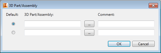
- Enter the part name or browse to it. Note: Rows are added as you add part names.
- Add an optional comment.
- Repeat if you have multiple parts you want to associate to this catalog value.
- Indicate which is the default part. The default part is inserted when you double-click a catalog value.
Important: The following sections cover editing catalog values that are currently used only in AutoCAD Electrical. Since the electrical catalog database is shared between AutoCAD Electrical and Inventor, these values can be edited in either program.
Assign an AutoCAD Electrical Schematic Symbol to a Catalog Value
- Locate the catalog record for the symbol.
- Click twice on the SYMBOL2D cell.
- Click to launch the 2D Symbol dialog box.
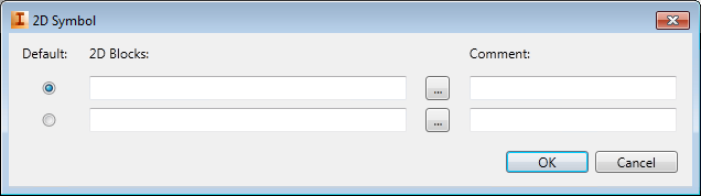
- Enter the block name or browse to it.
- Add an optional comment. Note: Rows are added as you add symbol names.
- Repeat for each block you want to associate to this catalog value. Include both horizontal and vertical versions.
- Indicate which is the default symbol. The default symbol is inserted when you double-click a catalog value while in insertion mode.
Edit Pinlist Values
- Locate the catalog value.
- Click twice in the COILPINS cell.
- Click to open the Coil Pins dialog box where you define the pins for the parent symbol.
- If the parent symbol has a contact state, for example a normally open pushbutton, select the contact type. If the parent symbol does not have a contact state, for example a relay coil, leave it as an undefined type.
- Enter the list of pins separated by a comma. The pin values are assigned in the order listed to the TERM# attributes on the component.
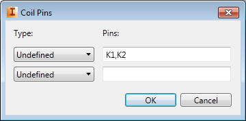
For example, if the value is "K1,K2", "K1" is assigned to the TERM01 attribute, and "K2" is assigned to the TERM02 attribute.
- Click twice in the PINLIST cell.
- Click to open the Pin List dialog box where you define the pins for the child symbols.
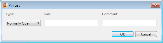
- Select the pin type from the available list.
- Enter the pin values separated by a comma or space. Note: Rows are added as you add pin values.
- Add an optional comment.
- Repeat for each set of pins associated with this catalog value.
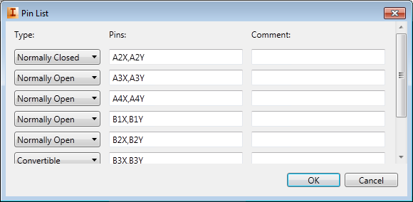
The pinlist is written to the database in the format required by the program, for example: 1,A1X,A1Y;2,A2X,A2Y;1,A3X,A3Y;1,A4X,A4Y;1,B1X,B1Y;1,B2X,B2Y;1,B3X,B3Y;1,B4X,B4Y.
- If the catalog value can have two parent symbols, for example forward and reversing starters, repeat the steps for the PEERCOILPINS and PEERPINLIST fields.
If this device can have child symbols define a PINLIST value.
Edit Terminal Properties
- Locate the catalog value in the TRMS table.
- Click in the LEVELS cell.
- Enter the number of levels for the terminal.
- Click to open the Terminal Properties dialog where you enter descriptions, pin values, and wires per connection for each level.
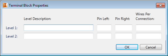 Note: The value in the LEVELS field controls the number of rows available on the dialog box.
 - To add or remove internal jumpers between levels:
- Click twice in the INTERNALJUMPER cell.
- Click to open the Manage Internal Jumpers dialog box where you add or remove jumpers between levels.
- Select the rows for the levels you want to jumper internally.
 Click to add the jumper.
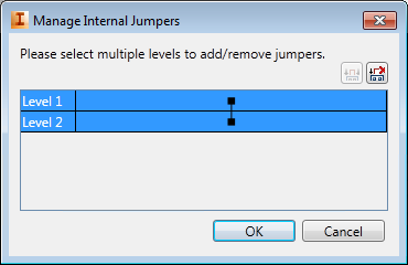
- Select the rows for the levels you want to remove a jumper.
 Click to remove the jumper.
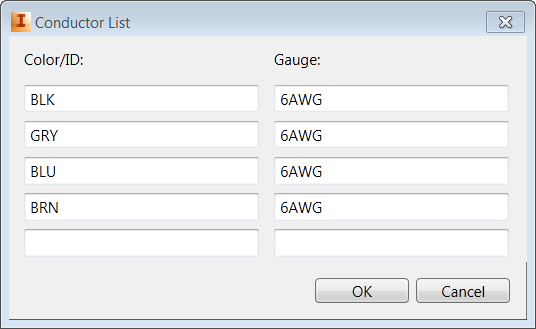
Edit Cable Conductor Lists
- Locate the cable you want to edit in the W0 table.
- Click twice in the CONDUCTORLIST cell. Note: A cable with conductors already defined displays "DEFINED" in the cell. A cable with no conductors defined displays "UNDEFINED" in the cell.
- Click to open the Conductor List dialog box where you add conductors and define the color and gauge for each conductor.
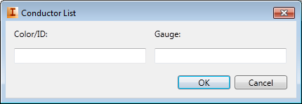
- Enter a color for the first conductor.
- Enter a gauge value for the first conductor. Note: Rows are added as you add color or gauge values.
- Repeat for each conductor in the cable.
Set up Subassemblies in the Catalog Database
Link a main catalog item with other subassembly items.
- Locate the catalog record for the main catalog item.
- Click the ASSEMBLYCODE cell.
- Select an existing value from the drop-down list or enter a new value. Spaces are allowed. Use multiple codes to link to multiple subassembly items. Note: Use a semi-colon, ";", to separate multiple codes. For example, NOBLOCK;NCBLOCK.
- Enter a number in the ASSEMBLYQUANTITY field to define the quantity of these subassembly items to include with the main catalog value. A blank value is the same as a 1. Note: to define a quantity for each subassembly when multiple ASSEMBLYCODE values are assigned, prefix the ASSEMBLYCODE value code with the quantity followed by a comma, ",". For example, 2,NOBLOCK;3,NCBLOCK.
- Locate the catalog record for the subassembly item.
- Click the ASSEMBLYLIST cell.
- Select the ASSEMBLYCODE value for the main catalog from the drop-down list.
- Enter a number in the ASSEMBLYQUANTITY field to define the quantity to include with this ASSEMBLYCODE.
Note: Subassembly catalog items must be in the same database table as the main catalog item.