In this exercise, you change the width of the polyline that represents the city limits. The city limits display more prominently in the drawing. Then you clip the image to display a rectangular portion that frames the city.
To change the width of a polyline
- If the CITY.dwg map is not still open, reopen it.
- Move your cursor over the city limits.
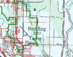
The green polyline represents the city limits.
Use the zoom commands on the View tab to zoom out to find the green polyline and then zoom in to select it.
- Click the polyline to select it.
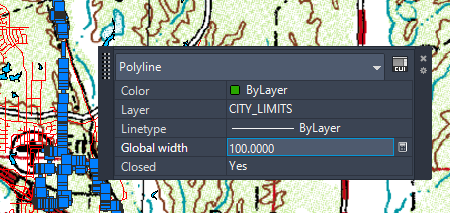
If the Quick Properties panel is not displayed, right-click anywhere in the drawing and select Quick Properties.
- Select the value for Global Width, enter
100.
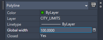
You can edit values in the Quick Properties window.
- Press
Esc to close the Quick Properties window.
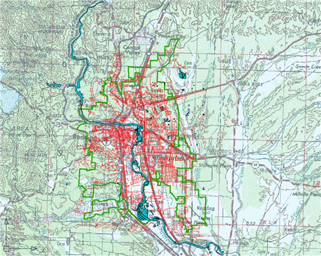
The polyline displays at the new width.
- Click

 Save.
Save.
To clip the image
- Zoom out so you can see the green polyline and the right edge of the raster image.
- Hold down the Shift key and click the edge of the image to select it.
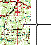
Shift-click the edge of the image to select it.
- Right-click the image and click ImageClip.
- Do the following to clip the image:
- In the prompt, click New Boundary.
- Click to specify the starting point of the boundary in the upper-left corner outside the city limits.
- Click to specify the opposite corner of the boundary outside the lower-right area of the city limits.
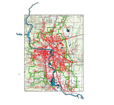
The raster image is clipped to the boundary you specified. The image displays only the portion within the specified boundary.
- Click
Save.
To continue this tutorial, go to Exercise 3: Add a raster image to a Display Manager layer.