
Using an overlay to display just the railway lines within the selected area.
There are three types of overlay analysis:
- Nodes with polygons
- Networks with polygons
- Polygons with polygons
To overlay topologies, both must be loaded into the current drawing.
Options for Overlaying Topologies
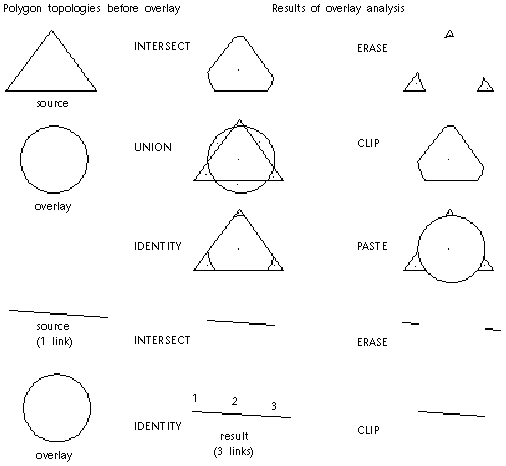
When you overlay two topologies, you choose the method in which the two selected topologies interact. In some cases, the result varies according to which topology is the source and which is the overlay.

Intersect
Intersect operations combine topologies and keep only the common geometry. Intersect acts like the Boolean AND operation. The results are the same whichever topology is chosen as the first or second. Object data is combined for the two operations.
Here are some examples of using Intersect:
- Which parcels (polygons) fall within 100-year flood zones (polygons)? Intersect shows only the flooded properties, not the whole property.
- Which crimes (nodes) fall within drug-free zones (polygons)?
- Which stream sections (networks) fall within the building area (polygons) and need to be examined for potential negative environmental impact?
Union
Union operations combine polygons with polygons and keep all geometry. Union acts like the Boolean OR operation and can be used only with polygons. For example, you can combine parcels with soils information for property assessment. Use Union to maintain both sets of geometry together and pull them apart as needed.
Identity
Identity operations work like Union on the source topology and like Intersect on the overlay topology. Use Identity to combine nodes, links, or polygons with polygons and keep all the input geometry. Identity creates one topology with one link where the link is crossed by the overlay topology.
When Identity is used with the question, Which parcels (polygons) fall within 100-year flood zones (polygons)?, all the properties in the flood zones are shown intact.
Erase
Erase operations use the overlay polygon topology like a mask and erase everything in the source polygon topology that is covered by the overlay topology.
Clip
Clip operations use the overlay polygon topology as a boundary. The parts of the source polygons outside the overlay polygons are clipped and discarded. You can use this option to show polygons within a boundary polygon, such as a city or state boundary.
Paste
Paste operations paste the overlay polygon topology on top of the source polygons. The source polygons not covered by the overlay remain. The Paste option can be used only with polygons.
Object Data in Overlay Analysis
You can copy selected object data and external database data from the source and overlay topologies to a new object data table in the resulting topology. You specify the name of the new object data table that will store the data in the resulting topology. The object data table name should be a new name. Data fields in the resulting topology look like this:
TOPONAME_FIELD
In addition to any fields you select, overlay analysis creates these object data fields in the resulting topology.
| Field Name | Data |
|---|---|
| TOPOID | Polygon Identification Number |
| TOPONAME1_ID | Object ID in source topology (TOPONAME1 is name of Source) |
| TOPONAME2_ID | Object ID in overlay topology (TOPONAME2 is name of Overlay) |
| TOPONAME1_PERCENTAREA | Percentage area of parent polygon in source topology |
| TOPONAME2_PERCENTAREA | Percentage area of parent polygon in overlay topology |