View the component, add boundary conditions, simulate the results, and optimize the part
- In the ribbon,
Actions panel, click
Create Component
 .
.
A model of the part is created, showing lattice and skin regions, with thickening of the lattice in the kernel area.
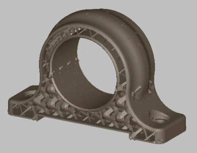
Note that some lattice bars are poking through the skin in a few places. We will address these after optimization.
- In the
Properties Panel, click the
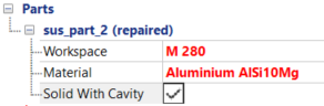
Simulation tab, then under the Part name, set the
Workspace to
M 280, and the
Material to
Aluminum AlSi10Mg.
- Right-click
, and then repeat, to create two boundary conditions.
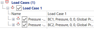
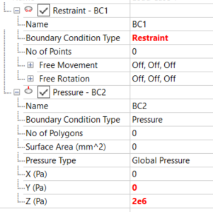
- Expand BC1 and set Boundary Condition Type to Restraint.
- Expand BC2. Leave
Boundary Condition Type as
Pressure, and
Pressure Type as
Global Pressure, then set the Pressure
Z value to
2e6.
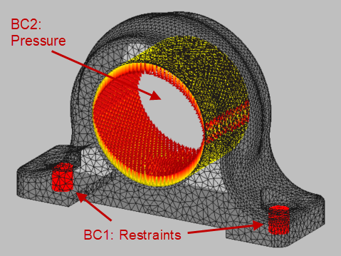
- Click BC1, and use Ctrl+Left Mouse to select a small group of points inside one of the small bolt holes on each side of the part. Use Ctrl+Left Mouse to select another group of points inside the other bolt hole.
- In the Selection panel, set the Tolerance value to 10, then click Flood Fill to select all points in the two holes (about 346 points).
- Click BC2, and select a small group of points inside the large hole in the part, then click
Flood Fill to select all the points inside the hole (about 3728 points).
Simulating the component
- In the Toolbar, click
Create Component
. After the component is created, click
Simulate Component
 .
.
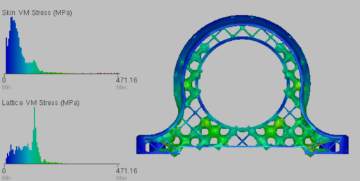
Initially, you see the Von Mises stress results, but you can also click Displacement in the FEA panel of the Toolbar to see Displacement results.
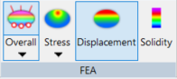
Simulation display options
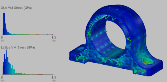
Skin and lattice stress results
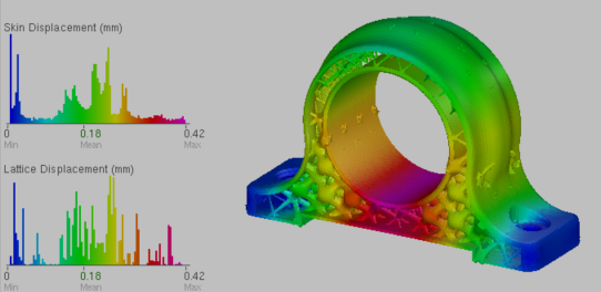
Skin and lattice displacement results
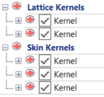
These simulation results are for the default component. You can also run simulations with components that embody Min and Max Thickness values for the lattice bars and skin:The Invert option on this menu creates a component in which thickness variations created by the kernels are inverted, so the thick regions are thinned, and thin regions are thickened. On the Parts tab of the Properties Panel, you can uncheck the kernels to disable them in a component for simulation.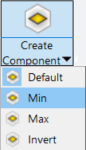
You can simulate a comparable solid part by selecting Solid Sim from the Simulate Component menu
 .
.
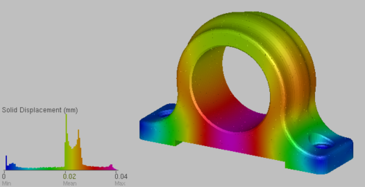
Solid part displacement results
Displacement of the solid part is much less than for the lattice and skin part. The project engineers can analyze these results, and if necessary, modify the lattice properties for greater stability.
Optimizing the component
- On the
Optimization tab of the Properties Panel, set the parameters for optimization as follows:
- Max Optimization Time (mins): 20
- Max Optimization Iterations: 40
- Lattice Max Allowable Stress (Pa): 200e6
- Skin Max Allowable Stress (Pa): 200e6
- On the Toolbar, click
Optimize Component, and the optimization run begins.
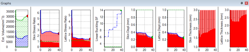
If you click the Component tab on the Properties Panel, you can see the Volume Reduction Coefficient value change as optimization proceeds.
In the final optimized part, note that the thickness of lattice bars has been redistributed in the part, as optimization has decided where greater strength is required.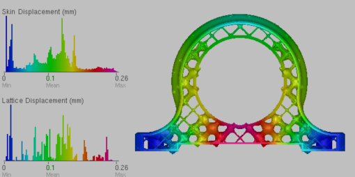
Post-optimization displacement results
Post-optimization stress results
A series of optimization graphs is generated below the display area.