- Select the part to be labeled.
- Click .
- Click the box in the context view labeled <no image> to open the file browser.
- Browse for an image file and click
Open. Supported file types include BMP, PNG, and JPEG.
Note: Black-and-white images work best. If you have gray or color images, drag the Threshold slider to adjust the gray scale.
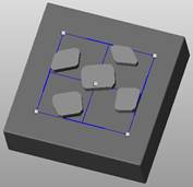
- Click on the part to view the label.
- Click and drag the blue nodes of the label to adjust the position, rotation, and size of the label.
Tip: Use the Ctrl key and the corner node to rotate the label without adjusting the size. Use the Shift key and the corner node to adjust the size without adjusting the orientation.
- Adjust the dimensions of the label as required.
- Choose a build type from the drop-down menu. Available options include:
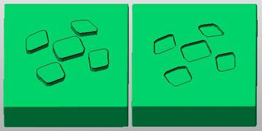
- Add to Part: Makes the label stand out from the part.
- Add to Part (inverted): Makes the label stand out from the part, but mirrors the text which can be useful for mold making.
- Subtract from Part: Engraves the label into the part surface.
- Subtract from Part (inverted): Engraves the label into the part surface, but mirrors the text which can be useful for mold making.
- Click Apply to create the text label.
- Click Yes to remove the old part or No to keep the old part and the newly labeled part.