Options and their function explained
Volume supports fill shadow volumes of downskins: The volume formed by projecting the downskin area towards the platform is filled with more or less dense, "sponge-like", volumetric support structures.
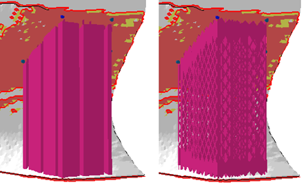
Left: Solid volume supports divided into fragments. Right: Volume supports built from a patterned structure.
Jump to:
Support properties
|
Filling Type |
Switch the support walls between Closed volume (solid) and Structure.
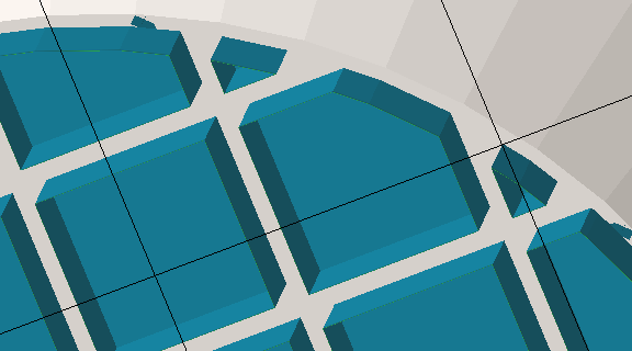 Applied default closed-volume supports. A cut via clip plane demonstrates the cluster's contour, the fragments' cross section, the terminating surface at the top, and the stand-off against the part surface.  Applied default Structure supports. Note the gap in the circumference. |
|
|
Top distance to part |
A stand-off distance between the upper end of supports and the part surface they connect with. Can be negative to sink support structure tips into the part if necessary. |
|
|
Bottom distance to part |
A stand-off distance between the lower end of supports and the part surface they connect with. Can be negative to sink support structure tips into the part if necessary. |
|
|
Stand Angle |
Support entities can be made conical with a wall angle of up to 45 ° from the vertical. To achieve the conicity, the angle is applied at the top, creating support that is either wider or narrower at the bottom.
Note: This applies to each support element individually and can produce a significant amount of self-intersections that may need cleaning up, especially when using this in conjunction with
Fragments.
|
|
|
|
Instead of being straight and angled, the closed-volume support's walls are formed into a concave curve towards the buildplate. At 0 %, the walls are straight and angled. At 100 %, the walls are vertical and terminate in a barrel fillet. Any value inbetween is a mix of the two. |
|
|
|
The lower this value (in millimeters), the finer the fillet is tessellated, smoothing the contour but also increasing the triangle count. |
|
|
Structure Properties |
Contains properties of the support entity walls, see details below. |
Jump to: |
|
Raster |
Settings for filling structures. See details below. |
|
|
Contour |
Settings for the outer enveloping contour of the support structure. See details below. |
|
|
Connection |
This group defines the connections between support, part, and platform ground. It is divided into multiple sub-groups, one for each possible combination of part or platform surface and support structure ends. See details below. |
|
|
Fragments |
Fragmentation creates gaps in normally continuous polyline support. Gaps make support easier to break off. See details below. |
|
|
|
Choose from three options to reshape the volume support to avoid or target other part surfaces (including no reshaping) using a hard knee shape or a smooth spline. |
|


Structure properties
|
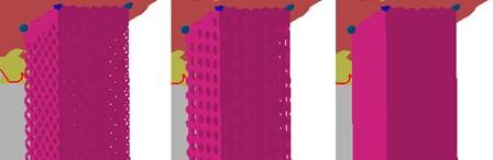
Structure pattern |
Switch between Wired wall (left), a Punched plate (middle), and Plain (right) to determine the wall pattern of volume supports.
|
|
|
Width and Height |
Width and height of the hole shapes. |
|
|
Interval width and height |
Distance between neighboring holes to the sides and to those above and below. |
|
|
Thickening up Structure-Hatches |
Volume support walls are merely such that they result in single-line toolpasses. To make the structures thicker, as in, inflate them into hollow structures, this value can be used Notes
|
Not available for solid supports. (Filling type Closed volume) |
|
Thickening up top connections |
If the structure is set to become thickened, a value can be set to specify the thickness of the top connections separately, allowing to create conical transitions between structure and part. |
|
|
Thickening up bottom connections |
If the structure is set to become thickened, a value can be set to specify the thickness of the bottom connections separately, allowing to create conical transitions between structure and part. |
|
|
Stitch tolerance |
Set a tolerance in millimeters up to which a gap between the structures is not going to be stitched. A value of 0.01 mm is recommended to keep as default. |
|
|
Maximum height |
Produces support structures only up to this length. Supports will end in mid-air, if necessary. |
|
|
Solid structure for height |
Over this distance from the bottom end of the support, structured support will have no pattern, only continuous surface. |
Has no effect for types other than Wired Wall and Punched Plate. |
|
Border width |
This overrides the width of the vertical fragment-lining strip as given by the connection properties value a in the illustration below. |
Can be set to 0 to have no such strip at all. A value of -1 disables the override. |
|
Fin |
Draws a single configurable right-angled fin from the middle of a polyline (or a polyline fragment, see Fragments section), strengthening the polyline support with a backbone. See Fins section. |
Does nothing for closed polylines (eg. created by Cluster-contour with polyline). |
|
Keep distance to wall |
Addresses cases when an undercut would cause a support structure to come closer to a wall than the cluster's wall offset can provide for. |
|
|
Use density map |
Toggles whether a volumetric heatmap should be applied to locally lighten or strengthen structures. |
|
| Fin | ||
|
Create fin |
Toggle fin creation. |
|
|
Width |
The fin will be this wide.
Note: If any
fragment shrinkage (see below) is specified, the width is scaled accordingly.
|
|
|
Keep distance to support |
Detach the fin from the support by this distance. |
|
|
Top distance to part |
The fin will end this distance short of terminating at the actual support's top end. |
|
|
Bottom distance to part |
The fin will end this distance short of terminating at the actual support's bottom end. |
Raster
The raster is built up from intersecting polyline walls and fills the actual volume of volume support.
|
Rotate by Z |
Sets the general alignment of filling structures. Filling structures are aligned globally, as in, against the platform coordinates. |
|
Hatch distance |
Sets the distance between the inner structure units. The number of inner structure units and the density will be affected.
Note: Not applicable to/available for
Closed-volume-type filling.
|
|
Filling strategy |
Defines in which directions the outer contours of the volume supports will be filled: In both X and Y direction, just in Y, or no filling at all. Notes
|
|
Distance to Contour |
To enforce a distance between the internal volume support entities and the enveloping polyline, set this beyond zero. If it is zero, the raster's walls terminate directly at the contour.
Note: This is always measured from the innermost contour, in particular if you have set
Contour count (see below) to values beyond 1.
|
Contour
The contour is an enveloping polyline that is used to provide a finish around the raster volume.
|
Contour count |
For values above 1, repeats the contour in concentric layers towards the inside. If no additional contour is requested, the volume-filling raster structures will terminate in the outer contour, touching it.
Note: These contours belong to the entire volume entity, even when you have disabled the rastering (the filling structures). To generate individual contour entities on clusters, use the separate support action
Cluster-contour with polyline instead.
|
|
Contour distance |
The gap between the envelope repetitions |
|
Smoothing distance |
Use this to adjust the mesh resolution of the contour to match the size of details of the supported skin. A very detailed skin, when sampled along its surface, may have details smaller than the sampling (effectively, the smoothing distance), so support connections may miss connecting with the surface in these spots. |
Connection
This group defines the connection between supports, part, and platform floor. It is divided into multiple sub-groups.
| Top part |
Refers to supports terminating in part surface at its top end. |
||
| Bottom part |
Refers to supports terminating in part surface at its bottom end. |
||
| Platform |
Refers to supports terminating in the platform surface at its bottom end. |
||
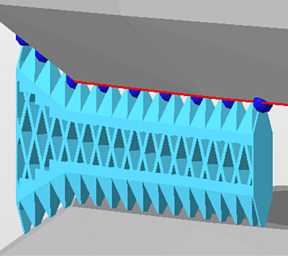
| Connection in Y |
This switch, when set to Yes, provides settings to specify a different type of support connections for those polylines that are aligned more towards the perpendicular of the Y axis rather than the perpendicular of the X axis. 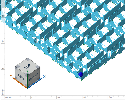 In this example, the volume-filling lines have a strip connection in one direction and pin connections in the other direction. |
||
| Connection by layer |
Clones the surface of the connection area, hugging its contours. See separate table on the parameters below. |
||
| Connection property | |||
|
Connection |
Type of connection |
Select from: Strip, Trapoid, Breaking Points, Triangles.
|
|
|
Connection width |
a |
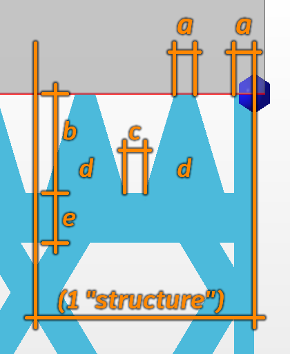 Connection properties |
The width of the vertical strip on the far right can be overridden. See . |
|
Connection height |
b |
|
|
|
Pin distance |
c |
|
|
|
Pins per structure |
d |
|
|
|
Distance connection to structure |
e |
|
|
| Platform connection | This section defines the connection between supports and platform ground. | ||
|
Connection |
Type of connection. See above for reference. |
||
|
Hatches |
Replicates the lower section of connections in parallel, up to 15 copies in each direction. This creates tapered, pedestal-like reinforcements. Accepts odd numbers up to 31 only, ignores even numbers. |
||
|
Hatch distance |
Distance between replications |
||
| Connection by layer | |
|---|---|
|
Create layer |
Toggles whether to use this type of connection. |
|
Refine layer |
If it is not possible to create a copy of the layer surface, the supported structure will be recreated through triangulation of anchor points. The higher this value, the higher the accuracy of the triangulation. |
|
Top layer height |
Defines the thickness of the layer. |
|
Top layer distance to structure |
Sets the distance between the top layer and the structure. |
|
Pin type |
The actual connection between the part and the layer is usually done with pins. Set the type of pins here by choosing from Cross or Cube. Alternatively, disable the pins entirely and connect the layer fully to the part. |
|
Pin width |
Determines the width of a pin. |
|
Pin density |
Determines the density of the pin structure. The smaller the value, the more pins will be created. |
Fragments
Fragmentation of volume supports into individual blocks makes it easier to break the supports from the part.
|
Raster |
|
|---|---|
|
Fragments |
Turn fragmentation on or off. |
|
Fragment size X |
Fragment size in X direction. |
|
Fragment size Y |
Fragment size in Y direction. |
|
Fragment gap |
Sets the gap width between volume-filling fragments |
|
X and Y shrinkage |
Shrinks the fragment at the bottom end, to have a wider fragment at top, whose size decreases to the set value |
|
Offset in X and Y |
Sets a distance by which to displace the raster-fragmenting gaps against the filling. Can also be negative. |
|
Contour |
|
|
Fragment contour |
The cluster-enveloping contour can be fragmented as well, using this toggle. |
|
Fragment contour length |
Defines the length of a fragment unit. |
|
Fragment contour gap |
Defines the gap width between two envelope polyline fragments |
|
Fragments |
Toggle whether the gaps in the enveloping contours should be aligned with the gaps that the fragments themselves have. |