Options and parameters explained
Once a cut plane or stencil is created, there are several tools available to adjust it and modify the result of the cut.
Note: Much of this functionality is unique to plane cuts. Only the cutting options are available for both plane and polygon cuts.
Jump to:
- Cut plane information
- Cut plane alignment options
- Cutting options
- Pins & holes: Cylinder
- Pins & holes: Hook
- Groove joinery
Cut plane information
- Base Point: Reports the coordinates of the center point of the plane.
- Move Parallel: Translates the plane by a specified distance so that it remains parallel to the current orientation.
-
Roll,
Pitch,
Yaw: Reports the roll, pitch, and yaw angles of the plane. Drag the slider or input an angle to adjust the orientation of the plane. The roll and pitch control the rotation of the cutting plane. The yaw determines the rotation of the plane around the vertical axis running through the center point.
Note: With a yaw of 90°, the side edges are rotated as well, although no apparent change is seen. The angles of roll and pitch are exchanged, compared to a yaw of 0°.
- Size: Reports the current size of the plane and allows you to input dimensions to adjust the size.
Cut plane alignment options
If you right-click a part, you can access four additional options to align the cut plane:
-
 Move Basepoint here: Moves the basepoint of the plane to the point you clicked on. The plane remains parallel to its previous orientation.
-
 Move Plane Parallel here: Moves the plane in a parallel fashion to the point you clicked on. The plane remains parallel and at a right angle to the previous orientation.
-
 Align Plane Parallel to this Face: Rotates the plane so that it is parallel to the face you clicked on.
-
 Align Plane Vertical to this Edge: Rotates the plane so that it is vertical to the selected edge.
Cutting options
- Only Selected Parts: When enabled, only selected parts are cut even when the plane or stencil goes through other parts as well.
- Use Plane Boundary: When enabled, the part is cut to the extents of the plane boundary. When disabled, the part is cut all the way through, regardless of the size of the displayed cut plane.
- Stitch Parts: When enabled, open triangle edges are connected.
- Automatic Pin Creation: Automatically creates pins and holes on the cut structures. These surface features are configurable.
- Remove Original Parts: Removes the original parts after the cutting operation.
- Close Cutting Area: When enabled, holes that emerge as a result of the cut are closed automatically with a flat surface across the cut.
- Create Group: When enabled, cut parts are grouped.
Pins & holes: Cylinder
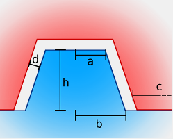
The cylinder-type pin is a cylindrical or conical stub.
General settings
- Height (h): The height of the pin above the surface.
- Distance of Pins (c): Distance between pins
- Min. Border Distance: Minimum distance between the edges of the surface and the pins
- Clearance (d): Distance between the pin and the hole
Cylinder settings
- Both Side Holes: Creates holes on both sides of the cut surface and no matching pins at all. Useful for when you want to provide your own dowels.
- Top Radius (a): Radius of the top surface of the cylinder
- Bottom Radius (b): Radius of the bottom surface of the cylinder
Pins & holes: Hook
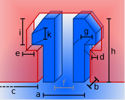
The hook-type pin is a pair of hooks that engages with a hole of matching contour and is, ideally, inseparable without destroying the hooks.
General settings
- Height (h): The height of the hook above the surface.
- Distance of Pins (c): Distance between hook pairs
- Min. Border Distance: Minimum distance between the edges of the surface and the hook pairs
- Clearance (d): Distance between the hook surface and the hole
Hook settings
- Depth (b): Depth of the hook
- Width (a): Width of the hook
- Nose Width (e): Width of the nose
- Hook Width (g): Width of the hook
- Spacing (f): Distance between hooks
- Nose Height (i): Height of the nose
- Tip of Nose Height (k): Height of the nose tip
Groove joinery
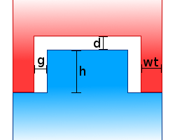
Groove joinery creates a single matching plug-and-socket arrangement of surface features that follows the contour of the cut.
Groove joinery settings
- Wall thickness (wt): Thickness of the rim
- Gap (g): Peripheral clearance between the two parts, seen along the parallel to the cut
- Height (h): Width of the nose
- Distance (d): Axial clearance between the parts, seen along the perpendicular to the cut
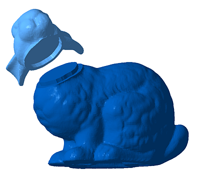
Plug-and-socket features to reassemble sections after a cut