In this exercise, we'll compare the results from the four exercises featuring the lever arm. With each iteration, we refined our assumptions and introduced additional load, mesh, and modeling techniques to incorporate greater physical realism into the analysis.
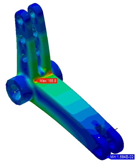
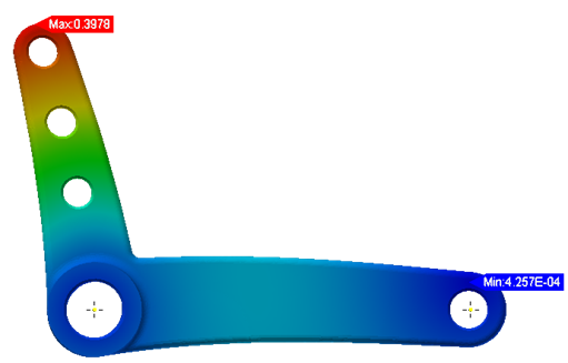
In the first exercise, we used basic boundary conditions (loads at the two ends and a constraint in the middle). We also used default mesh sizing. The results looked like this:


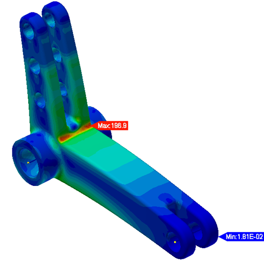
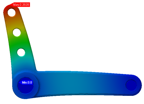
In the second and third exercises, we replaced the incorrect loads and constraints with advanced techniques to produce a more realistic deformation. These included rigid connectors and ball joint constraints. We also refined the mesh in critical areas to produce a solution that is dependent on the mesh. The resultant deformation is shown:


In the fourth exercise, we replaced the constraints with the actual pin parts, we used symmetry to constrain the rigid body motion, and we used contacts to model the interaction and movement between the lever arm and the pins. This combination of techniques produced the most physically realistic analysis scenario and resultant deformation:


Summary
Most of the techniques you will need to work with Autodesk Inventor Nastran were covered in these exercises. It is important to use boundary conditions and contacts correctly, as they can have significant effects on the validity of any design decisions made from FEA results. It is important to check convergence and apply consistent modeling practices if you are making design changes and comparing stress results. Be careful not to make design decisions based on false results from poor convergence.
|
Previous Topic: Results Visualization (Post-Processing) |
Next Topic: Nonlinear Static Analysis |