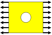
Digital Prototyping Solution
Autodesk Digital Prototyping is an innovative way for you to explore your ideas before they're even built. It's a way for team members to collaborate across disciplines. It's a way for individuals and companies of all sizes to get great products into market faster than ever before. From concept through design, manufacturing, marketing and beyond, Autodesk Digital Prototyping streamlines the product development process from start to finish.
Where does simulation fit within Digital Prototyping? Simulation adds the following capabilities to the Digital Prototyping cycle:
- It allows you to explore design options early in the design cycle.
- With simulation, you can predict product performance before expensive prototypes are created and tested.
- You can validate product designs so you know how your parts are going to behave in the field.
Why Do We Need FEA?
FEA adds substantial value to the product design process. It provides significant insight and design guidance that helps to create better products. Some of the specific benefits and outcomes of using FEA include the following:
- Predict performance for planned use.
- Predict potential failure with predictable abuse.
- Evaluate and correct observed failure.
- Improve performance and safety of a known design.
- Improve cost/weight of a known design.
- Develop new and innovative concepts.
- Gain insight into design concepts or directions.
- Modeling decisions should be driven by goals.
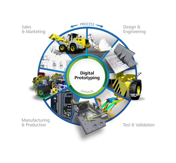
The Reason FEA Is So Powerful
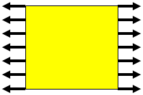
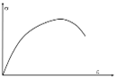
In this simple case, basic engineering equations describe the peak stress:
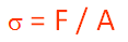
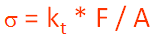
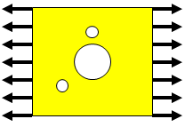
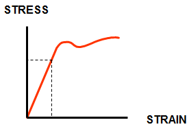
For a slightly more complex case, we can supplement basic engineering equations with stress concentration factors from a structures text (such as Roark) to determine peak stress:
However, with just a little more complexity, the engineering equations are no longer sufficient to determine peak stress. FEA is the best choice.

Basic FEA Concepts
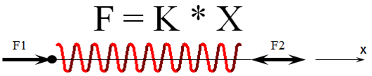
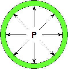
Force is determined from measured displacements:
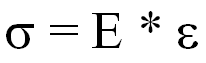
Stress is determined from measured displacements:
The FEA Process
|
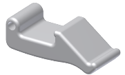
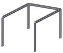
Step 1. Create Geometry |
|
|
Step 2. Assign Material Properties |
|
|
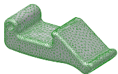
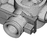
Step 3. Create Mesh |
|
|
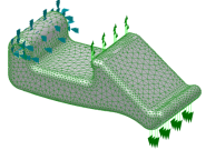
Step 4. Apply Loads and Constraints |
|
|
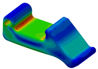
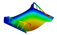
Step 5. Review Results Use the results to determine if design changes are required to reduce the chance of failure, improve performance, or optimize for cost. |
|
Modify design and/or conditions and repeat as necessary.
The Basic Assumptions in FEA Analysis
This section summarizes the assumptions needed when defining an FEA analysis. These include the analysis geometry, materials, meshing, loads, constraints and choosing the appropriate physics for the situation.
Modeling Idealizations
These are the primary 3D simulation and modeling idealizations:
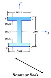
- Beam simulation
- Symmetry and anti-symmetry
- Plate or shell models
- 3D Solids
These are the primary cross-sectional idealizations:
- Plane stress
- Plane strain
Idealizations and Element Types
A finite element mesh consists of nodes and elements:
- Nodes are points in 3D space.
- Elements are areas or volumes defined by nodes:
|
Element Type |
Example Elements |
|---|---|
|
Solid Elements No element properties are required. |
|
|
Shell Elements Element thickness is required. |
|
|
Line Elements Cross section and orientation are required. |
|
Materials and Property Definitions
Properties serve two primary purposes in Autodesk Inventor Nastran:
- They reference materials.
- They are used to specify the element type used in the analysis.
Materials are the physical substances used in the model (aluminum, steel, etc.). You can either import them from a material library or input property data to define the material.
Material Properties
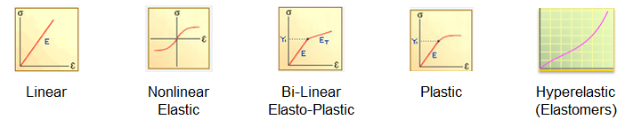
It is critical to use the appropriate material type. For linear analyses, the choices include:
- Isotropic
- Orthotropic
- Anisotropic
In some cases, you may need to use nonlinear materials instead. You should consider if it is feasible to idealize a nonlinear material as linear. Determine if you are in the linear elastic range or if you should be:
Geometry
There are two ways to add geometry to your analysis model:
- Open or import an existing CAD model.
- Create the geometry within the CAD environment.
These are some basic guidelines for geometry used for FEA analysis:
- A good mesh starts with good geometry.
- Consider building the geometry that matches the idealization you choose:
- Solids Elements - Solid Geometry
- Shell Elements - Surface Geometry
- Beam Elements - Wireframe Geometry
- Cross-Sectional Idealization - 2D Surface Patch
- Geometry provides a template for the mesh:
- Avoid sliver surfaces, narrow boundaries, small features.
Meshing Basics
- Not all meshes are good meshes:
- If mesh is too coarse (elements too large), model will be too stiff.
- Local stresses are most impacted.
- Convergence is the process of element size reduction where needed to ensure the proper response is calculated.
- All elements are not created equal:
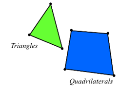
- All FEA solvers expect quadrilaterals to be squares and all triangles to be equilateral.
- Some variation acceptable - Gross variation causes error.
- The convergence process minimizes any potential error.
- Element recommendations:
- Line elements are always good - Convergence not required: Bars/Beams/Rods.
- Linear quad elements are preferred in most shell models. Inventor Nastran Shell mesher may insert triangles to complete the mesh based on geometry.
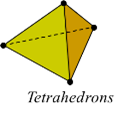
- Parabolic solid tetrahedrons are preferred. Linear tet elements behave too stiffly - OK for trend studies.
Boundary Conditions -- Loads and Constraints
Use boundary conditions to represent the interactions of the parts you didn't model with the parts you did. Your boundary conditions must not impose displacements, stresses, rigidity, or other behavior that the parts you didn't model wouldn't have imposed.
Incorrect use of boundary conditions is the most common source of error with users at all levels.
- Apply CAD-based boundary conditions to faces, edges, or vertices.
- For advanced boundary conditions, use rigid elements and body loads.
Some basic guidelines include:
Choosing the Appropriate Physics
Selecting the correct physics is essential for a successful and accurate analysis. It is good to consider the following:
- Static: Slowly applied, continuous load. Includes contact, contact with friction, large displacement/stress stiffening.
- Frequency: Distinct natural frequencies to understand vibration response.
- Dynamic: Actual response to time or frequency-based inputs.
- Buckling: Stiffness-related instability resulting from compression.
- Thermal: Temperature variation or flux.
- Drop Test: Impact of part or assembly with ground.
- Fatigue: Response to cyclic load; estimate life/durability.
- Nonlinear: Nonlinear stress-strain or path dependent behavior.
It is essential to understand the limitations of all solution types:
- Is my model and loading properly linear static?
- Is it a dynamic analysis?
- Is it nonlinear?
- Will buckling occur?
- Do temperatures influence loads, stiffnesses, or stresses?
Summary of FEA Basics
FEA basically solves F= Kx {F}=[K]{x} or P= Ma+Bv+Kx for dynamics.
Zero values in stiffness and mass will result in singularities, resulting in a solution that fails.
Autodesk Inventor Nastran can only answer questions you ask. The primary skill for success with FEA is engineering judgment. With this, all the simulation inputs can be properly quantified.
|
Previous Topic: Introducing Autodesk Inventor Nastran |
Next Topic: Cantilevered Beam Exercise |