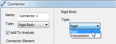
When you select the Rigid Body option under Type on the left half of the Connector form, you have a choice of two sub-types of rigid bodies. Choose this option using the Type drop-down menu in the Rigid Body section at the right half of the dialog.

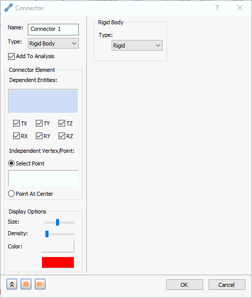
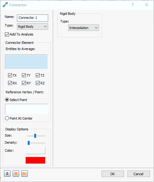
The appearance of the Connectors dialog differs slightly between the two rigid body types. Specifically, in the Connector Element section, the names of the selection boxes change (Dependent Entities and Independent Vertex/Point, for the Rigid type; Entities to Average and Reference Vertex/Point for the Interpolation type).
Connector dialog, Rigid Body, Type = Rigid:

Connector dialog, Rigid Body, Type = Interpolation:

-
Type:
- Rigid: Defines RBE2 (fully rigid) element types.
- Interpolation: Defines RBE3 (interpolation) element types. Typically used to distribute loads.
 Care must be used when defining Rigid (RBE2) and Interpolation rigid elements (RBE3). Careless creation can cause fatal errors.
 When using
RBE2 elements, the
Dependent entities will move exactly how the
Independent entities move. When using
RBE3 elements, the displacement of the reference nodes is the weighted average of the displacement of the
Entities to Average.
- Add To Analysis: This checkbox automatically puts this rigid body connector under Connectors in the current Analysis branch of the tree.
-
Connector Element section: Allows multiple rigid elements to be defined within the current connector
Name.
- Degrees of Freedom (DOF) checkboxes (TX, TY, TZ, RX, RY, and RZ): These are the active DOF for the rigid elements (that is, the translational and rotational directions in which they provide rigidity). By default, all six DOF are activated. Deactivate any translational or rotational DOF in which you want to allow relative motion between the Independent/Reference Point and the Dependent Entities/Entities to Average.
- When
Type = Rigid, you define…
- Dependent Entities and
- Independent Vertex/Point.
- When
Type = Interpolation, you define…
- Entities to Average and
- Reference Vertex/Point.
- Display Options: Allows you to edit the size, density, and color of the rigid body connector symbols displayed on the model.
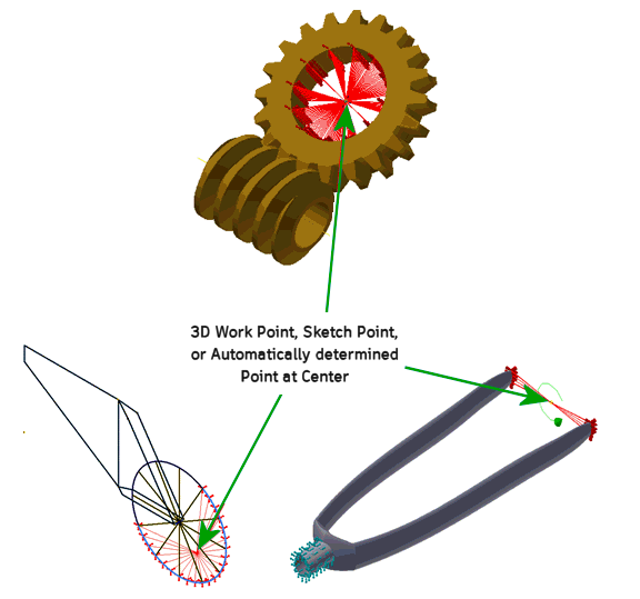
Rigid Body Connector Examples:
