Gap Element Property
Description: Defines the properties of gap elements (CGAP entry).
Format:

Example:

| Field | Definition | Type | Default |
|---|---|---|---|
| PID | Property identification number. | Integer > 0 | Required |
| U0 | Initial gap opening. See Figure 2 and Remark 1. | Real or AUTO | 0.0 |
| F0 | Preload. See Figure 2. | Real | 0.0 |
| KA | Axial stiffness for the closed gap (i.e. U A - U B > U0). See Figure 2. | Real > 0.0 | Required |
| KB | Axial stiffness for the open gap (i.e. U A - U B < U0). See Figure 2 and Remark 3. | Real ≥ 0.0 or blank | 10 -10 * KA |
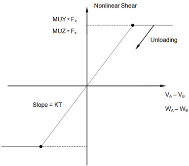
| KT | Transverse stiffness when the gap is closed. See Figure 3. It is recommended that KT ≥ (0.1 * KA). | Real ≥ 0.0 | MUY * KA |
| MUY | Coefficient of friction in the y transverse direction
 . See Remark 4. . See Remark 4.
|
Real ≥ 0.0 | 0.0 |
| MUZ | Coefficient of friction in the z transverse direction
 . See Remark 4. . See Remark 4.
|
Real ≥ 0.0 | 0.0 |
| TMAX | Maximum allowable penetration used in the adjustment of penalty values. A positive value activates the penalty value adjustment. See Remark 5. | Real | 0.0 |
| MAR | Maximum allowable adjustment ratio for adaptive penalty values KA and KT. See Remark 6. | Real > 1.0 | 100.0 |
| TRMIN | Fraction of TMAX defining the lower bound for the allowable penetration. See Remark 7. | 0.0 ≤ Real ≤ 1.0 | 0.001 |
Remarks:
- The default initial gap opening is zero. If AUTO or -1.0 is specified, the initial gap opening will be set to the initial element length. This is particularly useful when defining multiple gap elements over an uneven surface.
- Figures 1 through 3 show the gap element and the force-displacement curves used in the stiffness and force computations for the element.
- For most contact problems, KA (penalty value) should be chosen to be three orders of magnitude higher than the stiffness of the neighboring grid points. A much larger KA value may slow convergence or cause divergence, while a much smaller KA value may results in inaccurate results. The value is adjusted as necessary if TMAX > 0.0.
- When the gap is open, there is no transverse stiffness. When the gap is closed and there is friction, the gap has the elastic stiffness (KT) in the transverse direction until the friction force is exceeded and slippage starts to occur.
- There are two types of gap elements: adaptive gap and nonadaptive gap. If TMAX ≥ 0.0, the adaptive gap element is selected by the program. When TMAX = 0.0, penalty values will not be adjusted, but other adaptive features will be active (i.e., the gap-induced stiffness update, gap-induced bisection, and subincremental process). The recommended allowable penetration TMAX is about 10% of the element thickness for plates or the equivalent thickness for other elements that are connected to the gap.
- The maximum adjustment ratio MAR is used only for the adaptive gap element. Upper and lower bounds of the adjusted penalty are defined by:

where Kinitial is either KA or KT.
- TRMIN is used only for the penalty value adjustment in the adaptive gap element. The lower bound for the allowable penetration is computed by TRMIN * TMAX. The penalty values are decreased if the penetration is below the lower bound.
- This element will default to a linear spring in linear solutions with an axial stiffness equal to KA and a transverse stiffness equal to KT. A nonlinear solution must be selected for general contact behavior.

Figure 1. GAP Element Coordinate System

Figure 2. GAP Element Force-Deflection Curve for Nonlinear Analysis

Figure 3. GAP Element Shear Forces for Nonlinear Analysis