*RCTR
r1
r1: r*8: Recoater tolerance in %. Default 20%.
If the thickness of the powder layer is reduced due to distortion below r1% of the nominal layer thickness, a warning message is generated signaling a possible interference between the recoater blade and the build. Think of tolerance as a measure of clearance between the previous build and the recoater blade.
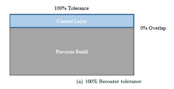
The figures below help illustrate how recoater tolerance is calculated. In Figure a, there is 0.040 mm allocated for the fusion of the next layer, and there is 0.040 mm on top of the build, which results in a 100% tolerance or clearance.

In Figure b, distortion of the previous build has taken up 0.006 mm or 15% of the tolerance, which results in 85% of tolerance remaining. This would be acceptable if your recoater tolerance was set to the default value of 20%.

In Figure c, there is a 0.0321 mm build overlap, taking up 81% of the tolerance, resulting in only 19% recoater tolerance remaining and a warning message, as the tolerance is below the threshold of 20%.

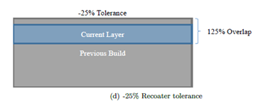
In Figure d, the build of 0.050 mm exceeds the entire recoater clearance of 0.040 mm for the current layer, so it returns a warning and a calculated interference of –25%. This loss of tolerance would almost certainly result in recoater blade damage.

Along with the log files, appended .out, the text file, file_name_recoater.txt is written after the mechanical simulation completes. This file records the time, layer group number, recoater clearance %, peak height of the deformed model at the top of the layer group, and the nominal recoater height at the top of the layer group. A sample file is shown below:
time (s), layer group, recoater clearance (%), top z deformed coord (mm), recoater coord (mm)
9.024533E+03           1      93.331     1.602668E+00     1.640000E+00
1.805244E+04           2      89.961     3.204015E+00     3.240000E+00
2.712766E+04           3      76.513     4.809395E+00     4.840000E+00
3.624973E+04           4      72.380     6.411048E+00     6.440000E+00
4.540336E+04           5      73.722     8.010511E+00     8.040000E+00
5.457021E+04           6      78.515     9.608594E+00     9.640000E+00
6.375136E+04           7      80.608     1.120776E+01     1.124000E+01
7.295711E+04           8      82.051     1.280718E+01     1.284000E+01
8.221741E+04           9      74.441     1.441022E+01     1.444000E+01
9.153668E+04           10     69.227     1.601231E+01     1.604000E+01
1.010004E+05           11     -1.821     1.764073E+01     1.764000E+01
1.106051E+05           12    -24.325     1.924973E+01     1.924000E+01
1.204665E+05           13      0.818     2.083967E+01     2.084000E+01
1.308714E+05           14      7.291     2.243708E+01     2.244000E+01
1.414172E+05           15      4.956     2.403802E+01     2.404000E+01
1.519087E+05           16     -4.642     2.564186E+01     2.564000E+01
1.624634E+05           17     -1.487     2.724059E+01     2.724000E+01
1.728352E+05           18     -2.322     2.884093E+01     2.884000E+01
1.830612E+05           19      8.865     3.043645E+01     3.044000E+01
1.932244E+05           20      6.861     3.203726E+01     3.204000E+01
2.032568E+05           21      4.110     3.363836E+01     3.364000E+01
2.133567E+05           22      2.824     3.523887E+01     3.524000E+01
2.229929E+05           23     -9.362     3.684374E+01     3.684000E+01
This example file shows that recoater interference is almost certainly going to be a problem for this build, starting from layer 11 onward. This is another feature to help guide the end user towards adding or strengthening support structures, changing building parameters, orientation, or part geometry to ensure that a useful part can be printed.