Thermal analysis
From a command line run
$ pan -b 03_thermal
The analysis progress is written to file 03_thermal.out. To check progress on Linux, run
$ tail 03_thermal.out
or in Windows run
$ type 03_thermal.out
After the analysis completes, the last few lines of the output file 03_thermal.out should be similar to the following:
 inc =        47 time =   14725.277     iter =   1 eps = 0.35216E+03
 inc =        47 time =   14725.277     iter =   2 eps = 0.61160E-12
Finished writing file results\ 03_thermal_47.case
Finished writing file results\ 03_thermal_47_c.case
Writing record:            2, time:      14725.2769198732
Increment end
CPU wall for increment 47 = 00:00:00.45, since start = 00:00:41.16
Layer end

Mesh preview volume  = 6800.88614359419
Activated volume     = 6800.88614359419
Activated percentage = 100.0000000000000

Finished writing file .\ 03_thermal.case
Finished writing file .\ 03_thermal_c.case

Analysis completed

****************************
1 Warning
****************************

CPU wall for printing = 00:00:20.71
CPU wall = 00:00:41.22
Approximate single thread simulation time = 00:10:22.93

Peak RAM used for this process = 269,624 kB

END Autodesk AM Process Simulation
Actual CPU times will differ.
Quasi-static mechanical analysis
Run the analysis from the command line:
$ pan -b 03_mechanical
After the analysis completes, the last few lines of the output file 03_mechanical.out should be similar to the following:
----------------------------------
Substrate removal time increment
----------------------------------
 inc =      49 time =    24725.277    iter =    1 eps =  0.48474E+04
 inc =      49 time =    24725.277    iter =    2 eps = 0.48469E-09

Optimizing rigid body motion...
Initial RMS displacement          =      2.210957E-01
Optimized RMS displacement        =      1.392428E-01
Number of optimization iterations =       218
Rotation matrix =
   1.000000E+000   4.498557E-005   1.701512E-004
  -4.508919E-005   9.999998E-001   6.090092E-004
  -1.701238E-004  -6.090169E-004   9.999998E-001
Translation =   -6.492318E-002   -7.589644E-002   1.197161E-001

Finished writing file results\ 03_mechanical_49_f.case
Finished writing file results\ 03_mechanical_49.case
Increment end
CPU wall for increment 49 = 00:00:01.51, since start = 00:00:58.86
Layer end

------------------------------------------------------
Total number of equilibrium iterations:       97

Mesh preview volume = 6800.88614359419
Activated volume = 6800.88614359419
Activated percentage = 100.0000000000000

Finished writing file .\ 03_mechanical_f.case
Finished writing file .\ 03_mechanical.case

Analysis completed

************************
   1 Warning
************************

CPU wall for substrate removal = 00:00:01.57
CPU wall = 00:00:58.92
Total thermal & mechanical simulation time = 00:01:40.15
Approximate single thread simulation time = 00:17:58.17

Peak RAM used for this process = 852,012 kB

END Autodesk AM Process Simulation
Actual CPU times will differ.
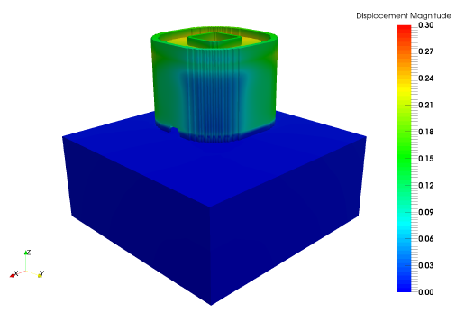
Results can be imported and viewed in the Simulation Utility for Netfabb or in ParaView. Figure 2 shows the computed final distortion before the part is removed from the substrate.

Figure 2 Final distortion results
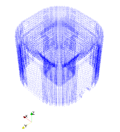
Two point cloud files are produced during the mechanical simulation: 03_mechanical_1.wrtu and 03_mechanical_2.wrtu, which are from the increments right before and after removal of the part from the build plate, respectively, for the nodes of the built component. These files have the format X, Y, Z, X displacement, Y displacement, Z displacement with all the units in mm. A visualization of the X,Y,Z point cloud is shown in Figure 3.

Figure 3: Point cloud file visualization