Use the Components dialog to specify the machine-housing and machine-part components displayed during Full Machine Simulation.
To display this dialog, click the Components button in the:
- Machine Data dialog (PartMaker/SwissCAM, PartMaker/Turn-Mill and PartMaker/Mill).
- Main Spindle Properties dialog (PartMaker/Swiss/CAM and PartMaker/Turn-Mill).
- Sub-Spindle Properties dialog (PartMaker/Swiss/CAM and PartMaker/Turn-Mill).
- Tool Post Properties dialogs (PartMaker/Swiss/CAM and PartMaker/Turn-Mill).
- Tool Head Properties dialog (PartMaker/Mill).
- Table Properties dialogs (PartMaker/Mill).
The following options are available:
1. 2. 3... — To display a component during Full Machine Simulation, select the numbered check box for that component. To add a new component, select the check box and then specify details for the component.
Name — The name of the component.
Motion Axes — Specifies the axes in which the component can move. Select a check box (X, Y, Z) if the component can move in that axis.
Rotation Axes — Specifies if the component can rotate:
-
B — Select this axis for a turret component that can rotate.
This option is available only if the B motion axis is selected for the turret in the Machine Data dialog and the turret has an XY Plane selected as the Turret Plane in the Tool Post Properties, Turret dialog.
-
R — Select this axis for a sub-spindle component that can rotate.
This option is available only if the R rotation axis is selected for the sub-spindle in the Machine Data dialog. You can specify further details about the axis and center point about which the sub-spindle rotates in the Sub-Spindle Rotation Options dialog.
Model Origin Coordinates — Specifies the coordinates of the component's solid model origin so PartMaker can position the component correctly during simulation.
- For a
stationery axis, the coordinates are relative to the origin of the machine.
PartMaker uses
 to denote a stationery axis).
- For a
moving axis, the coordinates are relative to the origin of the machine part; that is, the spindle, tool post, tool spindle or table.
PartMaker uses
 to denote a moving axis.
Model Data — Displays the Model Data dialog, where you can select the file containing the solid model of the component.
Example: Setting Motion Axes and Model Origin Coordinates for a turret with two components
The following diagrams illustrate how to set up the Motion Axes and Model Origin Coordinates for a turret with two components – a slide and a block:
Motion Axes:
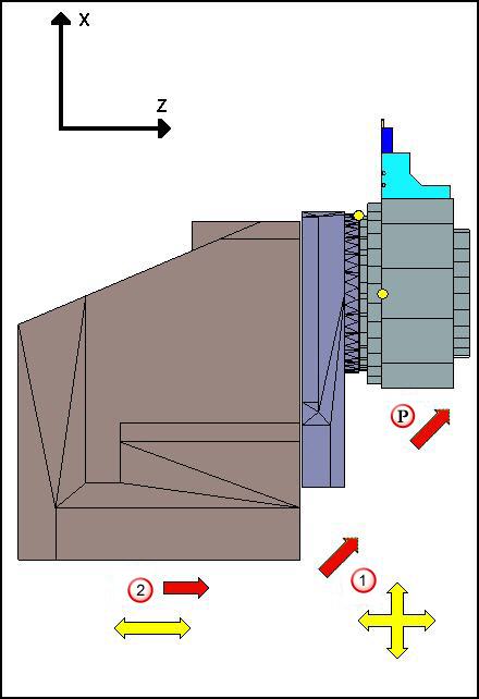
 The slide has both its X and Z axes enabled (shown by the yellow arrows).
 The block has only its Z-axis enabled.
 The turret moves in both the Z axis and the X axis (shown by the red arrows).
Because the slide has the Z and X axes enabled, it moves directly with the turret. The block only has its Z-axis enabled (X is disabled) so when the turret moves in the Z and X axes, the block follows only in Z while maintaining a constant X position.
Model Origin Coordinates
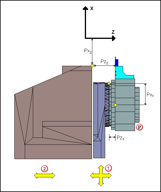
The slide has both its X and Z axes enabled (shown by the yellow arrows). Both its X-axis
Model Origin Coordinate (Px1) and its Z- axis
Model Origin Coordinate (Pz1) are relative to the origin of the turret ().
The block has its Z-axis enabled and its X-axis disabled. The Z-axis
Model Origin Coordinate (Pz2) is measured from the origin of the turret, as this axis is a moving axis. The X-axis
Model Origin Coordinate (Px2) is measured from the Machine Origin as the X-axis is a non-moving axis for the block component.