Use the Area Clearance Z Heights dialog to specify the Z heights at which the model is sliced during roughing.
To display the Area Clearance Z Heights dialog, click
 when specifying a manual stepdown for area clearance strategies.
This dialog contains the following:
-
Number — Select to divide the block equally into the specified number of Z heights, the lowest of which is at the bottom of the block. Displayed as
 in the list of Z heights.
-
Stepdown — Select to create a Z height at the top of the block and then steps down a defined height in Z. The final Z Height is at the bottom of the block. Displayed as
 in the list of Z heights.
- The Stepdown definition takes into account existing Z heights. This makes it easier to generate an optimum set of Z heights. So, PowerMill looks at pairs of existing Z heights and adds the minimum number of extra Z heights between them such that the stepdown between heights is less than or equal to the specified Stepdown.
-
Value — Select to add in additional Z heights at a specified height. Displayed as
 in the list of Z heights.
-
Intermediate — Select to add in additional Z heights between existing ones. Displayed as
 in the list of Z heights.
-
Flat — Select to identify flat areas of the model and creates Z heights on these areas. Displayed as
 in the list of Z heights.
 — Enter the number, distance or value of the Z heights.
Constant Stepdown - When selected, all the machining levels are equispaced, and the Stepdown value is a maximum stepdown. When deselected, the difference between consecutive machining levels is the Stepdown value for all levels except the last one which is at the bottom of the block.
Constant Stepdown deselected:

With a Stepdown of 20, the Z heights are at 15, -5, and -10.
The stepdown is the amount specified for all levels (in this case 20) except for the last one, which is at the bottom of the block (in this case a Stepdown of 5
Constant Stepdown selected:

With a Stepdown of 20, the Z heights are at 20, 5, and-10. This gives an effective stepdown of 15.
- The stepdown is the same between all levels but is not necessarily the amount specified. In this case, PowerMill uses a Stepdown of 15 rather than 20. This option is only available if you have a Defined by of Stepdown.
- Calculate — Click to calculate the values of the Z heights.
Reference enables you to append or delete the Z heights from other entities.
-
 Entity Type — Select the type of entity that is referenced when appending/deleting Z heights.
- Toolpath — This appends the Z heights defined in another toolpath. Displays the Z heights in the same way as for the reference toolpath in the list of Z heights.
-
Boundary — This appends a Z height at the highest and lowest point of the boundary. Displayed as
 in the list of Z heights.
-
Pattern — This appends a Z height at the highest and lowest point of the pattern. Displayed as
 in the list of Z heights.
-
Feature Set — This appends a Z height at the highest and lowest point of the feature set. Displayed as
 in the list of Z heights.
-
 Entity — Select which entity (for example, which toolpath) you want to reference.
-
 Action — Select how to reference the
Active Entity.
- Append All — If you select an entity of toolpath, this creates a Z heights at the same Z heights as the selected toolpath. If the entity is anything other than toolpath, then this creates Z heights at the highest and lowest point of the entity. These Z heights are added to those already created for this toolpath.
- Append Top — If you select an entity of toolpath, this creates a Z heights at the same Z height as the highest Z height in the selected toolpath. If the entity is anything other than toolpath, this creates a Z height at the highest point of the entity.
- Append Bottom — If you select an entity of toolpath, this creates a Z heights at the same Z height as the lowest Z height in the selected toolpath. If the entity is anything other than toolpath, this creates a Z height at the lowest point of the entity.
- Delete All — This deletes the Z heights contained in the entity from those in the new toolpath.
- Delete Top — If you select an entity of toolpath, this deletes the Z height at the same Z height as the highest Z height in the selected toolpath. If the entity is anything other than toolpath, this deletes the Z height at the highest point of the entity.
- Delete Bottom — If you select an entity of toolpath, this deletes a Z heights at the same Z height as the lowest Z height in the selected toolpath. If the entity is anything other than toolpath, this deletes the Z height at the lowest point of the entity.
- Find Common — This finds the Z heights that are common to the selected entity and this toolpath.
- Calculate — Click to calculate the Z heights from the referenced entity.
Delete by Picking enables you to delete Z heights by selecting them in the graphics window.
-
 Start Picking Mode — Select
 to activate the others buttons in the frame. This button is a toggle, so if the other buttons are active, clicking
 disables
 and
and
 .
.
-
 Delete the Selected Z Heights — Select a Z height in the graphics window, and click
 to delete it.
-
 Stop Picking Mode — Select
 to end the picking mode. The
 button becomes unavailable.
These options do not change the active toolpath. They are only using the information from the active toolpath to generate appropriate Z heights for the new toolpath.
List of Z Heights — This displays a list of the Z heights in the toolpath. The icon shows the creation method of the Z height.
-
 Defined by
Number
-
 Defined by
Stepdown
-
 Defined by
Value
-
 Defined by
Intermediate
-
 Defined by
Flat
-
 Defined by
Reference Boundary
-
 Defined by
Reference Pattern
-
 Defined by
Reference Feature Set
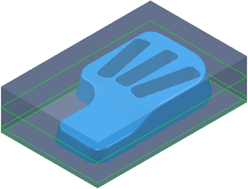
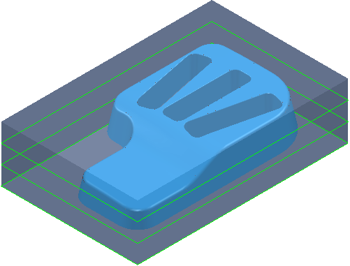
Draw — Select to display the Z heights used to create the area clearance toolpath.
 Delete — Click to delete the selected Z heights, if none are selected all the Z heights are deleted.