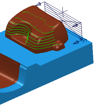
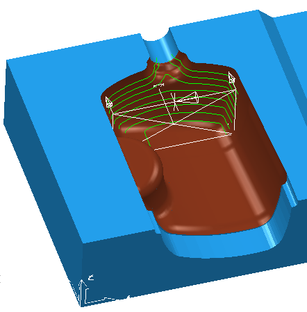
Use the Plane projection finishing page to project a planar pattern onto the model. This pattern is then machined.
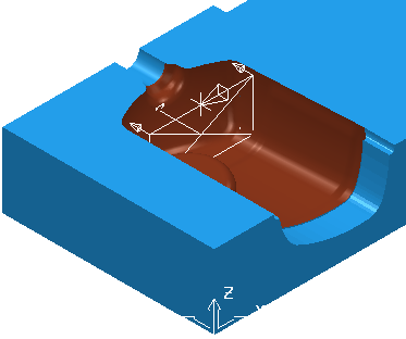
The plane technique produces a pattern on a plane. The plane can be rotated about the Z axis, and inclined to the vertical plane. The range of the pattern is described in terms of height and width limits.
Location XYZ — Enter the plane location. By default this is at the origin of the workpiece.
 — Click to display the
Position dialog. Use the dialog to manually enter coordinates and locate items in the graphics window.
— Click to display the
Position dialog. Use the dialog to manually enter coordinates and locate items in the graphics window.
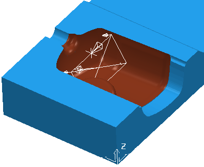
Azimuth — Enter the angle of the plane. The rotation is measured counter-clockwise about the Z axis with 0 in the ZX plane.
0
is in the XZ plane
90
is in the YZ plane
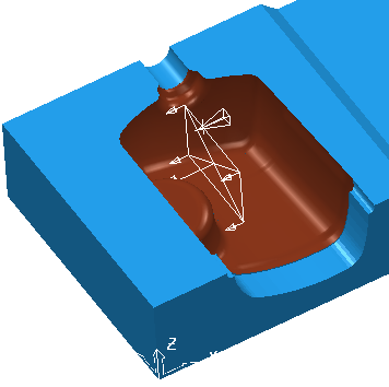
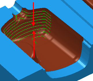
Elevation — Enter the angle of the plane to the vertical to produce a more effective finish over sloped areas of the model. Change the angle to project the pattern downwards onto the model.
0
is normal to the XY plane.
30
is at an inclination to the XY plane.
Direction — Select the direction to determine which regions are machined.
Select Inwards to machine cores . Typically the axis is behind the part.
Select Outwards to machine internal fillets, holes or cavities. Typically the axis is in front of the part.
Tolerance — Enter a value to determine how accurately the toolpath follows the contours of the model.
Thickness — Enter the amount of material to be left on the part. Click the
Thickness
 button to separate the
Thickness
box in to
Radial thickness
button to separate the
Thickness
box in to
Radial thickness
 Axial thickness
 . Use these to specify separate
Radial and
Axial thickness as independent values. Separate
Radial and
Axial thickness values are useful for orthogonal parts. You can use independent thickness on sloping walled parts, although it is more difficult to predict the results.
. Use these to specify separate
Radial and
Axial thickness as independent values. Separate
Radial and
Axial thickness values are useful for orthogonal parts. You can use independent thickness on sloping walled parts, although it is more difficult to predict the results.
Radial thickness — Enter the radial offset to the tool. When 2.5-axis or 3-axis machining, a positive value leaves material on vertical walls.

Axial thickness — Enter the offset to the tool, in the tool axis direction only. When 2.5-axis or 3-axis machining, a positive value leaves material on horizontal faces.

 Component thickness — Click to display the
Component thickness
dialog, which enables you to specify the thicknesses of the different surfaces.
Component thickness — Click to display the
Component thickness
dialog, which enables you to specify the thicknesses of the different surfaces.
Stepover — Enter the distance between successive machining passes.
Preview — Click to produce a quick preview toolpath over the projection shape.

Draw — Select to display the preview pattern.