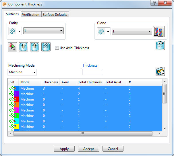
The Surfaces tab enables you to assign thicknesses to components, such as model surfaces. You can specify a single thickness or a separate Axial Thickness and Radial Thickness. You can also assign different thicknesses to components, depending on the toolpaths or boundaries that use them.
Use the Entity area to associate the thickness data with a specific toolpath or boundary. The Entity area contains the following options:
 — Select toolpath
 or boundary
 to associate thickness data with either a toolpath or a boundary.
 — Select an entry from the list to determine the toolpath or boundary to which the current set of component thicknesses refers. This list contains either toolpaths or boundaries, depending on your selection in the drop-down list.
Use the Clone area to copy all the thickness data from an existing toolpath, boundary, or verification set The Clone area contains the following options:
 — Select an option from the list to specify whether the component thicknesses data is cloned from a toolpath
, verification set
— Select an option from the list to specify whether the component thicknesses data is cloned from a toolpath
, verification set
 .or a boundary
.
.or a boundary
.
— Select the toolpath, boundary or verification set from the list that has the component thickness you want to clone. This list contains either toolpaths, verification sets or boundaries, depending on your selection in the drop-down list.
 — Click to copy the thickness data from the target.
 Smart Selection — Click to display the
Selection dialog. Use the
Selection dialog to select model components by
Model,
Colours, and
Levels and Sets and assign them to a thickness set.
Smart Selection — Click to display the
Selection dialog. Use the
Selection dialog to select model components by
Model,
Colours, and
Levels and Sets and assign them to a thickness set.
 Acquire Components — Click to place the selected components into the selected thickness set.
 Remove Components — Click to remove the selected components from the selected thickness set or sets.
 Remove All Components — Click to remove all the components from the selected thickness set or sets.
Use Axial Thickness — Select this option so you can select separate Radial and Axial Thickness values. When deselected, you can only select a single Thickness.
 Copy Default Data — Click to copy the values defined on the
Surface Defaults tab. When you create a new set of thickness data for a toolpath or boundary, the values currently in the
Surface Defaults tab are automatically copied into this dialog. If you change the
Surface Defaults, the
Component Thickness values are not automatically updated unless you click
Copy Default Data.
Copy Default Data — Click to copy the values defined on the
Surface Defaults tab. When you create a new set of thickness data for a toolpath or boundary, the values currently in the
Surface Defaults tab are automatically copied into this dialog. If you change the
Surface Defaults, the
Component Thickness values are not automatically updated unless you click
Copy Default Data.
 Select Components — Click to select all the components in the selected thickness set or sets.
Machining Mode — Select an option to specify how the component thickness is applied. The selection determines the colour displayed in the Mode column of the Thickness List Control table. Choose from:
- Machine — Select to add component thickness to a component which the toolpath will machine.
- Collision — Select to add component thickness to a component which will not be machined but must be avoided (such as a clamp).
- Ignore — Select to add component thickness to a component which will not be machined and was created only for construction purposes (such as a guiding surface used in multi-axis machining).
Thickness — Enter a value to apply thickness as an offset to the tool in all directions. This is available if the Use Axial Thickness is deselected.
- Radial Thickness — Applies the thickness as an offset to the tool radially. This controls the size of tool used for machining relative to the actual tool. This option only becomes available if Use Axial Thickness is selected.
- Axial Thickness — Enter a value to apply the thickness as an offset to the tool in the tool axis direction only. This controls the tip position of the tool used for machining relative to the actual tool. This option only becomes available if Use Axial Thickness is selected.
Thickness List Control — By selecting a thickness set, it determines the colour of the components when Thickness Shaded:
Set — The icon displayed shows whether the set is a toolpath or a boundary.
Mode — This displays the type of machining mode selected for these components. A series of colours are used to indicate the different modes:
- Machine — White
- Collision — Yellow
- Ignore — Red
-
Selected — Grey(when the graphics window has focus) or blue (when the
Thickness dialog has focus).
To change these default colours, select Tools > Customise Colours and then select Machining Mode in the Customise Colours dialog.
Thickness — The thickness values (or Radial Thickness) applied to the tool component.
Axial — The Axial Thickness values applied to the tool component.
Total Thickness — The combined thickness values (or Radial Thickness) applied to the component. The value is generated from adding the thickness values applied using this tab and the strategy dialogs.
Total Axial — The combined axial thickness values applied to the component. The value is generated from adding the thickness values applied using this tab and the strategy dialogs.
Components — This displays the number of components in the set.
For information on how to assign thicknesses to a set of components, see Assigning Thickness values.
For information on how to avoid specific areas of a model, see Machining Mode example.