The Ramp Options dialog enables you to specify how the tool ramps into the stock.
There are a variety of Ramp Option dialogs:
First Lead In Ramp Options dialog available by clicking the
Ramp Options
 button:
- In the Separate first lead in area of the Lead ins tab of the Toolpath connections dialog.
- In the Separate first lead in area of the First and last leads page of a strategy dialog.
Lead In Ramp Options dialog available by clicking the
Ramp Options
 button:
- On the Lead ins tab of the Toolpath connections dialog.
- On the Lead in page of a strategy dialog.
Lead Out Ramp Options dialog available by clicking the
Ramp Options
 button:
- On the Lead outs tab of the Toolpath connections dialog.
- On the Lead out page of a strategy dialog.
Last Lead Out Ramp Options dialog available by clicking the
Ramp Options
 button:
- In the Separate last lead out area of the Lead outs tab of the Toolpath connections dialog.
- In the Separate last lead out area of the First and last leads page of a strategy dialog.
These dialogs are all similar. The Lead In Ramp Options dialog and Lead Out Ramp Options dialog have two tabs: 1st Choice and 2nd Choice. The First Lead In Ramp Options dialog and Last Lead Out Ramp Options dialog aren't tabbed dialogs.
The 1st Choice and 2nd Choice tabs offer the same functionality, enabling you to create an alternative Ramp move (Toolpath, Line or Circle). For example, if you select a Lead In of Ramp which PowerMill cannot create because it gouges, then the alternative ramp move specified in the 2nd Choice tab is used. If this also gouges PowerMill tries your 2nd Choice option on the Lead Ins tab of the Toolpath connections dialog.
Follow — Select how to control the direction of the ramp.
Toolpath — The ramp moves follow the profile of the toolpath.

Line — The ramp moves are normal to the cutting direction at that point. If the requested line cannot be fitted into the area, then the Toolpath option is used automatically.

Circle — The ramp moves are circular. If the requested circle cannot be fitted into the area, then the Line method is used automatically.

Max Zig Angle — Enter the angle of descent formed as the tool ramps into the block.
Closed Segments Only — When selected, the ramp moves are inserted only into closed toolpath segments.
Circle Diameter (TDU) — Enter the diameter of the circle using tool diameter units (TDUs).
Ramp Height — This is measured relative to the tool axis. For 3-axis machining, the tool axis is the Z axis. For multi-axis machining, the tool axis is specified on the Tool Axis dialog.
Type — Select how to determine the height from which the ramp descends.
- Incremental — The height above the cleared stock for the start of the ramp.
- Segment — The start of the ramp is at the same height as the end of the previous toolpath segment, provided that this is higher than the toolpath segment by the amount specified in the Height field.
-
Segment Incremental — The start of the ramp is at the same height as the end of the previous toolpath segment plus the height specified in the
Height
field.
Note: The ramp always begins from a height which is equal to or greater than the height specified in the Height field plus the height of the toolpath segment.
Height — Enter the height of the start of the ramp above the option selected in the Type box.
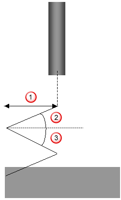
Length — Enter the maximum ramp length. This determines the number of zig and zag moves required in the ramp. This value is represented in Tool Diameter Units.

 Ramp length
 Zig angle
 Zag angle
Independent zag angle — When selected, you can enter a different Zag Angle from the Zig Angle. When deselected, the Zag Angle is the same as the Zig Angle. The second angle of descent is used if the tool doesn't reach the start of the toolpath segment in a single pass.
Maximum — Enter the angle of descent formed as the tool ramps into the block. This is specified in the same way as the Zig Angle (see Length).
Extend — Select to extend the ramp moves at the start or end of a toolpath. If you select a Follow of Toolpath, this option extends a Ramp Lead In (or Lead Out) to the end (or start) of its associated toolpath segment.
Always Ramp — Select to always ramp into the first point of a segment which is inside the block. This replaces plunge moves with ramp moves. This option is available only on the Lead In Ramp Options dialog.