Use the Start and End Point tab of the Toolpath connections dialog to specify the location of the tool at the start and end of the toolpath.
This tab contains the following settings:
Start point and End point
Use the options to define the location of the tool at the start or end of the toolpath:
Use —Select the location of the start or end point.
-
Block Centre Safe — The start/end point is at Safe Z above the block centre.
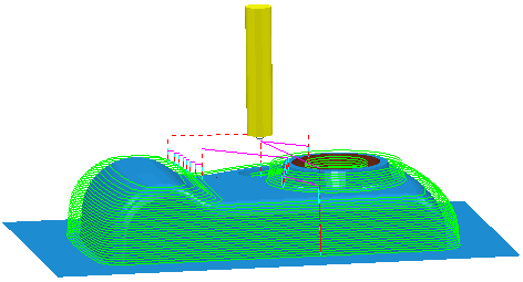
-
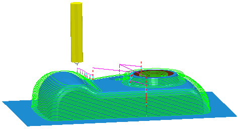
First / Last point safe — The start / end point is at Safe Z above the first / last point in the toolpath. For multi-axis toolpaths, the start point is set by considering a point that is the specified distance from the first point on the toolpath, measured along the tool axis, and projecting this onto the Safe Z area.
-
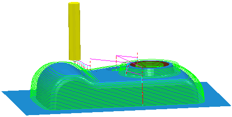
First / Last point — The start / end point is positioned at the specified distance from the first / last point in the toolpath, measured along its tool axis.
-
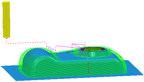
Absolute — The start /end point is positioned independently of all other properties at the point defined by the
Coordinates field.
Incremental plunge — When selected the approach move starts to plunge at an incremental distance from the start of the first lead in or cutting move.
Direct move — When selected, the tool moves directly from the specified start point to the start of the first lead in or cutting move, if it is safe to do so.
Override tool axis — Select this option to define a different Tool Axis orientation for segments other than the first or last segment. When selected, the Tool Axis area becomes available.
Motion — Select an option from the list to specify how the tool axis changes as it moves from the start / end point. These options are only available whenever the tool axis may change along the toolpath.
The following options behave differently depending on whether the tool is approaching the start point or retracting at the end point:
|
Motion |
Start point |
End point |
|
Simultaneous |
The tool axis is free to move along its path away from the start point. |
The tool axis is free to move along its path towards the end point. |
|
Move then rotate |
Safe area paths — The tool moves to the position above its target within the safe area, then changes the tool axis when it leaves the safe area. Direct paths — The tool moves directly to the end of the approach path and then changes the tool axis. |
The tool axis is fixed until it reaches the end of the retract path. |
|
Rotate then move |
The tool axis aligns with the first lead in or cutting move at the start of the approach path before any move is made. |
Safe area paths — The tool aligns with the axis specified at the end point when it reaches the safe area and then moves to the end point. Direct paths — The tool axis aligns with the end point at the start of the retract move. |
|
Rapid surface normal |
The tool axis is fixed perpendicular to the safe area as it moves across it. This option is only available for toolpaths that travel through the safe area. |
The tool axis is fixed perpendicular to the safe area as it moves across it. This option is only available for toolpaths that travel through the safe area. |
|
Reset machine tool |
The tool axis is kept aligned to the machine tool's initial orientation until the tool reaches the specified approach distance from its target. |
After the specified retract distance, the machine tool resets to its initial orientation. |
Separate approach / retract — Select this option to define the first approach or final retract moves differently from the approach and retract moves in other rapid links.
-
Approach / Retract along — Select an option from the list to define the direction of the first approach and final retract moves.
Tool axis — The First approach and Final retract moves have the same orientation as the tool axis.
Contact normal — The First approach and Final retract moves are normal to the contact point. This option is not available if the toolpath is not generated with contact normals.
Tangent — The First approach and Final retract moves approach along the tangential direction.
Radial — The First approach and Final retract moves approach along the direction radial to the tool axis.
- Approach / Retract distance — Enter the length of the approach or retract move at the start or end of the toolpath.
Incremental plunge distance — Specify how to measure the plunge moves relative to a target rather than the plunge surface. This option is only available for the start point.
- Distance — Enter the distance above the start of a toolpath segment at which to stop a rapid plunge, and to perform a controlled approach to the toolpath
-
Measured from — Select an option to specify how the distance to the start of the plunge move is measured:
- Toolpath point — Measures the incremental distances for plunge-moves relative to the start of the toolpath segment (current Z height).
- Stock — Measures the incremental distances for plunge-moves relative to the stock height at the start of the toolpath segment.
Coordinates — Enter the coordinates to define the position of the start or end point. This option is only available when you select a Use of Absolute.
 — Click to display the
Position
dialog. Use the dialog to manually enter coordinates and locate items in the graphics window.
— Click to display the
Position
dialog. Use the dialog to manually enter coordinates and locate items in the graphics window.
Tool axis — Define the Tool axis of the start and end point of a multi-axis toolpath. This option is only available if you have selected Override tool axis.
 — Click to display the
Direction
dialog, which enables you to edit the direction of an item.
— Click to display the
Direction
dialog, which enables you to edit the direction of an item.
 Lock — Use this buttonas a toggle to determine whether or not the start or end point is updated when changes are made to values that were used to create the point.
— The start or end point is unlocked, so it is recalculated whenever any of the values upon which it depends are changed. For example, for a block-dependent start point, a change in Safe Z causes a recalculation of the start point.
 — The start or end point is locked until you recalculate it on the
Start and end point tab. The options in the
Start point or
End point areas are unavailable when the appropriate point is locked.
— The start or end point is locked until you recalculate it on the
Start and end point tab. The options in the
Start point or
End point areas are unavailable when the appropriate point is locked.
Apply start / end — Click to save your changes and recalculate the start or end point.
Gouge check — Select this option for PowerMill to gouge-check all leads and links.
Apply both — Click to save your changes and recalculate both the start and end points.
Apply — Click to accept the values on the current tab and continue displaying it.
Accept — Click to accept the values on the dialog and close the dialog.
Cancel — Click to close the dialog without updating the start and end points.