Use the items on the Toolpath tab > Draw panel to draw and view various aspects of the active toolpath.
Toolpath
Click Toolpath tab > Draw panel > Toolpath to draw the active toolpath.
Links
Click Toolpath tab > Draw panel > Links to draw the links for the active toolpath.
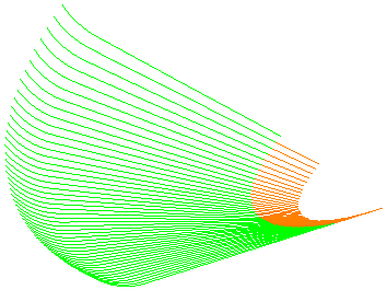
Toolpath with cutting moves, leads and links drawn:

Toolpath links not drawn:
Leads
Click Toolpath tab > Draw panel > Leads to draw the toolpath leads for the active toolpath.
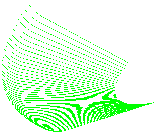
Toolpath cutting moves and leads drawn, but toolpath links not drawn:
Toolpath links not drawn:
Display
Use the following options in the Toolpath tab > Draw panel > Display menu to draw toolpath elements:
-
Cutting Moves — Draws the toolpath cutting moves for the active toolpath.
Toolpath with cutting moves, leads and links drawn:
Toolpath cutting moves not drawn:
-
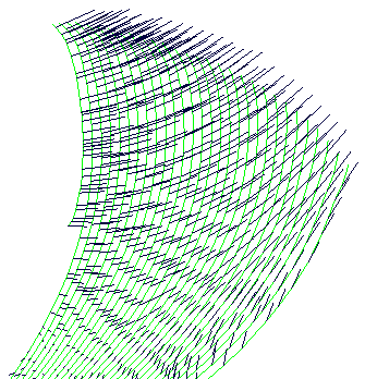
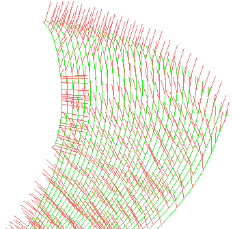
Tool Axes — Draws the axis of the tool at each toolpath point so that you can visualise the changing tool orientation:
-
Contact Normals — Draws the toolpath contact normals at each toolpath point in red.
 dialog. The contact normals are the
I, J, K vectors.
dialog. The contact normals are the
I, J, K vectors.
-
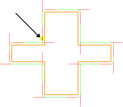
Orientation Normals — Draws the tool orientation vector.
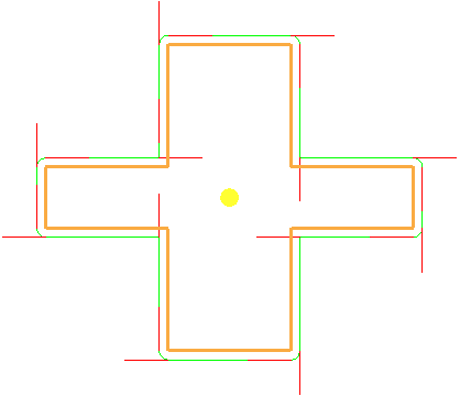
If you combine this with simulating the toolpath (using Simulate from start on the individual toolpath menu),
 shows the tool orientation.
-
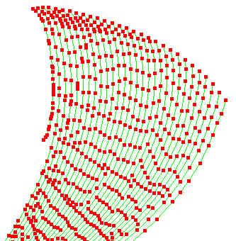
Points — Draws each toolpath point for the active toolpath in red, and draws the arc centres in blue. These are used for visualisation of point density.
-
Feeds — Draws the cutting moves with different colours which represent the feed rate in those areas as a percentage of the default feed rate.
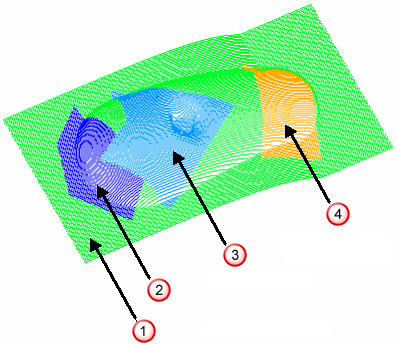
-
 Feed rate 100%
-
 Feed rate 40%
-
 Feed rate 60%
-
 Feed rate 150%
-
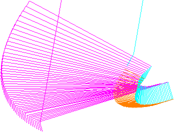
- Rapid Surface — Draws the surface of the safe area.
-
Plunge Surface— Draws the surface beyond which the plunge moves are made. This is the region of space beyond which approach moves are made at the plunge rate.
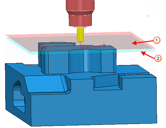 Rapid surface drawn, with an opacity of
25.
Plunge surface drawn, with an opacity of
25.
Rapid surface drawn, with an opacity of
25.
Plunge surface drawn, with an opacity of
25.
- Compensated Toolpath — Draws the toolpath showing full radius or wear compensated toolpath.
-
Contact Track — Draws the trace of the toolpath contact points in red.
Note: This option is available only if you select Contact Normals on the Point Distribution dialog. The contact normals are the
I, J, K vectors.
- Colliding Sections — Draws the colliding sections of the toolpath in a different colour. Colliding sections are those between the part and the tool, the holder, or the machine. Click Home tab > Verification panel > Colliding Sections to display a list of colliding sections for the active toolpath.
View by Z Height
Click Toolpath tab > Draw panel > View by Z Height to enable you to view the active toolpath at a specific Z height.