You can split an existing collision group within a kinematic chain into multiple collision groups that can be collision checked against one another.
The kinematic chain is the section in an .mtd file that contains the information that defines the behaviour of the axis-components (the moving parts) of a machine tool or, in this case, a robot.
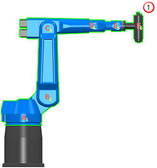
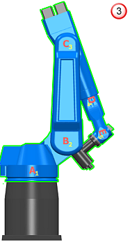
Often, the axis-components of a machine tool are grouped in one collision group. This means for the following robot
 , with its axis-components in one collision group
 ,
PowerMill does not recognise this orientation of the robot (like many other orientations) as a collision
 .
.


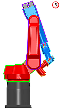
By splitting the collision group into multiple collision groups, you can collision check axis-components against one another. With the collision group split into multiple collision groups
 ,
PowerMill now recognises the same orientation of the robot as a collision
 .
.


PowerMill collision checks these axis-components:
- A against C, D, E, and F.
- B against D, E, and F.
- C against A, E, and F.
- D against A, B, F.
- E against A, B, and C.
- F against A, B, C, and D.
For more information, see Splitting a collision group.